With an old jacket, an Arduino Lilypad, some leds with integrated resistors, and some patience, my kid Giulio became the school star for one day.
He was super happy.
@mgua
.


/* ledcap lilypad Marco Guardigli I dressed a winter cap with an arduino lilipad mgua@tomware.it this code is GPL. see www.gnu.org */ #include---------------#define LEDFC 10 // front center #define LEDFR 11 // front right #define LEDFL 9 // front left #define LEDBR 19 // back right #define LEDBL 6 // back left #define MCLR 16 // multicolor led: Blue (when low) #define MCLB 17 // multicolor led: red (when low) #define MCLG 18 // multicolor led: green (when low) #define SPK 5 // speaker int melody[] = { NOTE_C4, NOTE_G3, NOTE_G3, NOTE_A3, NOTE_G3, 0, NOTE_B3, NOTE_C4 }; int noteDurations[] = { 4,8,8,4,4,4,4,4 }; // note durations: 4 = quarter note, 8 = eighth note, etc.: void sing() { Serial.println("sing"); for (int thisNote = 0; thisNote < 8; thisNote++) { // to calculate the note duration, take one second divided by the note type. //e.g. quarter note = 1000 / 4, eighth note = 1000/8, etc. int noteDuration = 1000/noteDurations[thisNote]; tone(SPK, melody[thisNote],noteDuration); // to distinguish the notes, set a minimum time between them. // the note's duration + 30% seems to work well: int pauseBetweenNotes = noteDuration * 1.30; delay(pauseBetweenNotes); // stop the tone playing: noTone(SPK); } } void setup() { Serial.begin(9600); Serial.println("Init"); pinMode(LEDFC, OUTPUT); pinMode(LEDFR, OUTPUT); pinMode(LEDFL, OUTPUT); pinMode(LEDBR, OUTPUT); pinMode(LEDBL, OUTPUT); pinMode(MCLR, OUTPUT); pinMode(MCLG, OUTPUT); pinMode(MCLB, OUTPUT); pinMode(SPK, OUTPUT); digitalWrite(LEDFC,LOW); digitalWrite(LEDFR,LOW); digitalWrite(LEDFL,LOW); digitalWrite(LEDBR,LOW); digitalWrite(LEDBL,LOW); digitalWrite(MCLR,HIGH); // multicolor led is off when the inputs are all high digitalWrite(MCLG,HIGH); digitalWrite(MCLB,HIGH); digitalWrite(SPK,LOW); delay(1000); sing(); } // RGB // LLL purple // HLL orange // LHL deeppurple // LLH light blue // LHH blue // HHL red // HLH green // HHH off void rainbow() { Serial.println("rainbow"); for (int i=1; i < random(100); i++) { if (random(100)>50) { digitalWrite(MCLR,LOW); } else { digitalWrite(MCLR,HIGH); } if (random(100)>50) { digitalWrite(MCLG,LOW); } else { digitalWrite(MCLG,HIGH); } if (random(100)>50) { digitalWrite(MCLB,LOW); } else { digitalWrite(MCLB,HIGH); } delay(50); digitalWrite(MCLR,HIGH); digitalWrite(MCLG,HIGH); digitalWrite(MCLB,HIGH); delay(50); } } void allblink() { Serial.println("allblink"); for (int i=1; i < random(100); i++) { digitalWrite(LEDFC,HIGH); digitalWrite(LEDFR,HIGH); digitalWrite(LEDFL,HIGH); digitalWrite(LEDBR,HIGH); digitalWrite(LEDBL,HIGH); delay(random(100)); digitalWrite(LEDFC,LOW); digitalWrite(LEDFR,LOW); digitalWrite(LEDFL,LOW); digitalWrite(LEDBR,LOW); digitalWrite(LEDBL,LOW); delay(random(100)); } } void randomblink() { Serial.println("randomblink"); int lev = random(100); for (int i=1; i < random(100); i++) { if (random(100) > lev) { digitalWrite(LEDFC,HIGH); } if (random(100) > lev) { digitalWrite(LEDFR,HIGH); } if (random(100) > lev) { digitalWrite(LEDFL,HIGH); } if (random(100) > lev) { digitalWrite(LEDBR,HIGH); } if (random(100) > lev) { digitalWrite(LEDBL,HIGH); } delay(random(100)); digitalWrite(LEDFC,LOW); digitalWrite(LEDFR,LOW); digitalWrite(LEDFL,LOW); digitalWrite(LEDBR,LOW); digitalWrite(LEDBL,LOW); } } void spinleft() { Serial.println("spinleft"); int d = random(500); int d1 = random(100); digitalWrite(LEDFC,HIGH); delay(d); digitalWrite(LEDFL,HIGH); delay(d1); digitalWrite(LEDFC,LOW); delay(d); digitalWrite(LEDBL,HIGH); delay(d1); digitalWrite(LEDFL,LOW); delay(d); digitalWrite(LEDBR,HIGH); delay(d1); digitalWrite(LEDBL,LOW); delay(d); digitalWrite(LEDFR,HIGH); delay(d1); digitalWrite(LEDBR,LOW); delay(d); digitalWrite(LEDFC,HIGH); delay(d1); digitalWrite(LEDFR,LOW); delay(d); digitalWrite(LEDFC,LOW); } void spinright() { Serial.println("spinright"); int d = random(100); int d1 = random(50); digitalWrite(LEDFC,HIGH); delay(d); digitalWrite(LEDFR,HIGH); delay(d1); digitalWrite(LEDFC,LOW); delay(d); digitalWrite(LEDBR,HIGH); delay(d1); digitalWrite(LEDFR,LOW); delay(d); digitalWrite(LEDBL,HIGH); delay(d1); digitalWrite(LEDBR,LOW); delay(d); digitalWrite(LEDFL,HIGH); delay(d1); digitalWrite(LEDBL,LOW); delay(d); digitalWrite(LEDFC,HIGH); delay(d1); digitalWrite(LEDFL,LOW); delay(d); digitalWrite(LEDFC,LOW); } void front3() { Serial.println("front3"); int ton=random(50); int toff=random(500); for (int i = 1; i < 10; i++) { digitalWrite(LEDFC,HIGH); digitalWrite(LEDFR,HIGH); digitalWrite(LEDFL,HIGH); delay(ton); digitalWrite(LEDFC,LOW); digitalWrite(LEDFR,LOW); digitalWrite(LEDFL,LOW); delay(toff); } } void loop() { // cycles random effects switch (random(10)) { case 0: rainbow(); break; case 1: if (random(100) > 90) { sing(); } break; case 2: allblink(); break; case 3: spinleft(); break; case 4: spinright(); break; case 5: front3(); break; case 6: randomblink(); break; default: delay(1000); } delay(1000); }
/*
Web Server, Pulse Logger, NTP time client, for Carcano spa
31.10.2011
This code is GPL. see www.gnu.org for details
be careful in increasing string space. this software uses almost all the arduino ATMEGA328 memory (2Kb)
SDcard Datalogger v0.8
mgua@tomware.it
fgentili@tomware.it
Arduino-Ethernet:
TCPIP Webserver with
NTP client
Asynchronous Interrupt (IRQ0) pulse counter on Digital pin2
DataLogger on Micro SDcard file
* Ethernet shield attached to pins 10, 11, 12, 13
* Analog inputs attached to pins A0 through A5 (optional)
* Digital input with raising front pulse counter on digital PIN2
NTP protocol is used to sync from a time server
in arduino 022 download time.zip
http://www.arduino.cc/playground/Code/Time
http://www.arduino.cc/playground/uploads/Code/Time.zip
and put its contents in
libraries/DS1307RTC
libraries/Time
libraries/TimeAlarms
SDcard is accessed via SPI protocol standard, which is also used to program ethernet Wiznet controller.
In order to interact with SD, we need to set pin10 as output otherwise SD library will not work
*/
#include
#include
#include
#include
#include
byte mac[] = { 0xDA, 0xAD, 0xBE, 0xEE, 0xFE, 0xED };
byte ip[] = { 10, 2, 3, 51 };
byte mask[] = { 255, 255, 0, 0 };
byte gateway[] = { 10, 2, 0, 1 };
byte timeServer[] = { 10, 2, 3, 60 };
// seconds to add to UTCtime to consider correct timezone
// const unsigned long UTCcorrection = 7200; // CET = UTC + 1 (+2 in summer): (HOW to properly calculate DST?)
const unsigned long UTCcorrection = 0; // keep UTC
const int NTP_PACKET_SIZE= 48; // NTP time stamp is in the first 48 bytes of the message
byte packetBuffer[NTP_PACKET_SIZE]; // buffer to hold incoming and outgoing packets
unsigned int localPort = 8989; // local port to listen for UDP packets
Server server(80); // local listener port for http services
// variable for pulsecounter, to be altered from inside interrupt routine (requires volatile)
volatile unsigned long pulses = 0;
int pulsePin = 2; // use pin2 for async pulse counter IRQ0 is connected to PIN2, (IRQ1 is connected to pin 3)
const unsigned long seventyYears = 2208988800UL;
unsigned long epoch = seventyYears;
const int EthChipSelect = 10;
const int SDChipSelect = 4;
time_t logInterval = 10UL; // append to file every loginterval seconds
time_t lastLogTime = 0UL;
time_t syncInterval = 60UL; // ntp sync every syncinterval seconds
time_t lastSyncTime = 0UL;
unsigned long logLinesWritten = 0;
const int maxLogLines = 7;
boolean fileFull = false;
char* logFileName = "log.txt";
unsigned long logFileSize = 0; //logfilesize added from last powerup
unsigned long sendNTPpacket(byte *address) {
memset(packetBuffer, 0, NTP_PACKET_SIZE); // set all bytes in the buffer to 0
// Initialize values needed to form NTP request
packetBuffer[0] = 0b11100011; // LI, Version, Mode
packetBuffer[1] = 0; // Stratum, or type of clock
packetBuffer[2] = 6; // Polling Interval
packetBuffer[3] = 0xEC; // Peer Clock Precision
// 8 bytes of zero for Root Delay & Root Dispersion
packetBuffer[12] = 49;
packetBuffer[13] = 0x4E;
packetBuffer[14] = 49;
packetBuffer[15] = 52;
// Now send packet requesting a timestamp to server udp port NTP 123
Udp.sendPacket( packetBuffer,NTP_PACKET_SIZE, address, 123);
}
void ntpTimeSync() {
sendNTPpacket(timeServer); // send an NTP packet to a time server & wait if a reply is available
delay(1000);
if ( Udp.available() ) {
Udp.readPacket(packetBuffer,NTP_PACKET_SIZE); // read the packet into the buffer
// the timestamp starts at byte 40 of the received packet and is four bytes,
// or two words, long. First, esxtract the two words:
unsigned long highWord = word(packetBuffer[40], packetBuffer[41]);
unsigned long lowWord = word(packetBuffer[42], packetBuffer[43]);
// combine the four bytes (two words) into a longint: NTP time (seconds since Jan 1 1900)
unsigned long secsSince1900 = highWord << 16 | lowWord;
// NTP gives secs from 1 1 1900. Unix time starts on Jan 1 1970. In seconds, that's 2208988800:
// subtract seventy years:
epoch = secsSince1900 - seventyYears;
Serial.print("T=");
} else {
Serial.print("Te!");
}
Serial.println(epoch);
time_t t = epoch + UTCcorrection;
setTime(t); // sets arduino internal clock
}
String getTimeString() {
// gives back hh:mm:ss
time_t t = now();
String s = "";
if (hour(t) <10) s = s + "0";
s = s + hour(t) + ":";
if (minute(t) <10) s = s + "0";
s = s + minute(t) + ":";
if (second(t) <10) s = s + "0";
s = s + second(t);
return(s);
}
String getDateString() {
// gives back dd/mm/yyyy
time_t t = now();
String s = "";
if (day(t) <10) s = s + "0";
s = s + day(t) + "/";
if (month(t) <10) s = s + "0";
s = s + month(t) + "/";
s = s + year(t);
return(s);
}
void tic() { // IRR Interrupt response routine, bump counter when signal raising front seen
pulses++;
}
void setup()
{
Serial.begin(9600);
Serial.print("R:");
Serial.println(FreeRam());
// setup interrupt logic
pinMode(pulsePin, INPUT); // non strettamente necessaria, in quanto IRQ0 e' sempre agganciata a pin2
attachInterrupt(0, tic, RISING); // LOW-CHANGE-RISING-FALLING tic is the function pointer to the RRI
Serial.println("I");
Ethernet.begin(mac,ip,gateway,mask);
Udp.begin(localPort);
Serial.println("E");
ntpTimeSync();
Serial.print("SD");
pinMode(EthChipSelect, OUTPUT);
if (!SD.begin(SDChipSelect)) {
Serial.println("e!");
while(1); // fatal: wait forever
}
Serial.println();
Serial.println("H");
server.begin();
Serial.println("-");
}
void webServer() {
// sends log content if something is specified
String creq;
Client client = server.available();
if (client) {
while (client.connected()) {
if (client.available()) {
char c = client.read();
if (c != '\n' && c != '\r') {
creq += c;
continue;
}
}
Serial.print("[");
Serial.print(creq);
Serial.println("]");
if (creq[5] != 'x' && creq[5] != 'X') { // http://172.30.4.47/x or http://172.30.4.47/X requests log, else std page
client.println("HTTP/1.1 200 OK");
client.println("Content-Type: text/html");
client.println();
client.print("TomWare PulseLogger 0.8");
client.println("http://ip/X ->log");
client.println("
");
client.print("T:");
client.print(getTimeString());
client.println("");
client.print("D:");
client.print(getDateString());
client.println("
");
client.print("p2 pulses:");
client.print(pulses);
client.print("
");
client.print("log:");
client.print(logFileName);
client.println("
");
client.print("lines:");
client.print(logLinesWritten);
client.println("
");
client.print("logsize:");
client.print(logFileSize);
client.println("
");
client.print("ram:");
client.print(FreeRam());
client.println("
");
} else { // LOG REQUESTED
File dataFile = SD.open(logFileName, FILE_READ);
if (! dataFile) {
client.println("HTTP/1.1 404 Not Found");
client.println("Content-Type: text/html");
client.println();
client.println("File Not Found!");
}
Serial.println("W");
client.println("HTTP/1.1 200 OK");
client.println("Content-Type: text/plain");
client.println();
char k;
while ((k = dataFile.read()) > 0) {
client.print((char)k);
}
dataFile.close();
if (fileFull) { // start a new file if file full, deleting contents just sent
Serial.print("D");
SD.remove(logFileName);
Serial.println(".");
fileFull = false;
}
}
delay(1); // give the web browser time to receive the data
client.stop();
}
}
}
void logToFile() {
// always log to logFileName file
File logFile = SD.open(logFileName, FILE_WRITE);
if (logFile) {
String s = "";
time_t t = now();
s = String(t) + "," + String(pulses);
for (int analogChannel = 0; analogChannel < 6; analogChannel++) {
s += ",";
s += String(analogRead(analogChannel));
}
logFile.println(s);
logFileSize = logFile.size();
logFile.close();
Serial.println(s);
logLinesWritten++;
} else {
Serial.println("SDe!");
while(1); // fatal: wait forever
}
}
void loop() {
webServer();
time_t t = now();
if ((t - lastLogTime) >= logInterval) {
lastLogTime = t;
Serial.print("F:");
Serial.println(FreeRam());
Serial.print("L:");
Serial.println(logLinesWritten);
logToFile();
if ((logLinesWritten % maxLogLines) == 0) {
Serial.println("FF");
fileFull = true;
}
}
if ((t - lastSyncTime) > syncInterval) {
lastSyncTime = t;
Serial.println("N");
ntpTimeSync();
}
}


(Last updated on aug 30 2011)
Configuration of Red Hat Enterprise Linux Server 6.1 (Hardware: HP DL380G7, 2 CPU Intel core) connected with two 10Gbit/sec ethernet interfaces (HP NC522SFP Dual Port 10GbE Server Adapter Board), with interface bonding, high availability, bandwidth aggregation and multiple VLAN transport.
Two 10Gbit/s physical network interfaces have to be connected to two FEX (Nexus Fabric EXtension "switches") upstreaming to two different Nexus 7000 cores, in a high availability configuration, allowing also to use both links simultaneously, and to transport different VLANs.
The different VLANs have then to be mapped on different linux logical subinterfaces.
The two physical interface are joined to form a bond, called bond0.
A specific channel configuration exists on the cisco nexus switches, so to allow these ports to form a single trunk channel, and to transport on it tagged frames from the selected VLANs, complying to the 802.1q transport.
Here are the settings on the Cisco Nexus Side (only one "side" is shown, the other is symmetric):
Core to FEX2232

  interface port-channel131
    switchport
    switchport mode fex-fabric
    fex associate 131
    mtu 9216


  FEX to server

  interface Ethernet131/1/5
    description srv
    switchport
    switchport mode trunk
    switchport trunk allowed vlan 10-13
    flowcontrol send off
    channel-group 88 mode active
    no shutdown
-------
[root@srv network-scripts]# cat ifcfg-eth0
DEVICE=eth0
USERCTL=no
ONBOOT=yes
MASTER=bond0
SLAVE=yes
BOOTPROTO=none
HWADDR=78:e3:b5:f4:e0:50
TYPE=Ethernet
IPV6INIT=no

[root@srv network-scripts]# cat ifcfg-eth2
DEVICE=eth2
USERCTL=no
ONBOOT=yes
MASTER=bond0
SLAVE=yes
BOOTPROTO=none
HWADDR=78:E3:B5:F4:76:E0
TYPE=Ethernet
IPV6INIT=no


[root@srv network-scripts]# cat ifcfg-bond0
DEVICE=bond0
BOOTPROTO=none
ONBOOT=yes
TYPE=Ethernet
BONDING_OPTS="mode=4 miimon=100"
IPV6INIT=no
USERCTL=no
MTU=9000


[root@srv network-scripts]# cat ifcfg-bond0.10
IPADDR=192.168.145.248
NETMASK=255.255.254.0
DEVICE=bond0.10
ONBOOT=yes
VLAN=yes
TYPE=Ethernet
HWADDR=78:e3:b5:f4:e0:50
BOOTPROTO=none
GATEWAY=192.168.144.1
IPV6INIT=no
USERCTL=no
MTU=1500

[root@srv network-scripts]# cat ifcfg-bond0.11
IPADDR=192.168.148.85
NETMASK=255.255.255.0
DEVICE=bond0.11
ONBOOT=yes
VLAN=yes
TYPE=Ethernet
BOOTPROTO=none
IPV6INIT=no
USERCTL=no
MTU=9000


[root@srv network-scripts]# ifconfig eth0 && ifconfig eth2 && ifconfig bond0 && ifconfig bond0.10 && ifconfig bond0.11
eth0      Link encap:Ethernet  HWaddr 78:E3:B5:F4:E0:50
          UP BROADCAST RUNNING SLAVE MULTICAST  MTU:9000  Metric:1
          RX packets:30750 errors:0 dropped:0 overruns:0 frame:0
          TX packets:12992 errors:0 dropped:0 overruns:0 carrier:0
          collisions:0 txqueuelen:1000
          RX bytes:3590043 (3.4 MiB)  TX bytes:3577302 (3.4 MiB)
          Interrupt:53

eth2      Link encap:Ethernet  HWaddr 78:E3:B5:F4:E0:50
          UP BROADCAST RUNNING SLAVE MULTICAST  MTU:9000  Metric:1
          RX packets:36472 errors:0 dropped:0 overruns:0 frame:0
          TX packets:7248 errors:0 dropped:0 overruns:0 carrier:0
          collisions:0 txqueuelen:1000
          RX bytes:27483898 (26.2 MiB)  TX bytes:906669 (885.4 KiB)
          Interrupt:61

bond0     Link encap:Ethernet  HWaddr 78:E3:B5:F4:E0:50
          inet6 addr: fe80::7ae3:b5ff:fef4:e050/64 Scope:Link
          UP BROADCAST RUNNING MASTER MULTICAST  MTU:9000  Metric:1
          RX packets:67224 errors:0 dropped:0 overruns:0 frame:0
          TX packets:20242 errors:0 dropped:0 overruns:0 carrier:0
          collisions:0 txqueuelen:0
          RX bytes:31074081 (29.6 MiB)  TX bytes:4484967 (4.2 MiB)

bond0.10  Link encap:Ethernet  HWaddr 78:E3:B5:F4:E0:50
          inet addr:192.168.145.248  Bcast:192.168.145.255  Mask:255.255.254.0
          inet6 addr: fe80::7ae3:b5ff:fef4:e050/64 Scope:Link
          UP BROADCAST RUNNING MASTER MULTICAST  MTU:1500  Metric:1
          RX packets:51880 errors:0 dropped:0 overruns:0 frame:0
          TX packets:13135 errors:0 dropped:10 overruns:0 carrier:0
          collisions:0 txqueuelen:0
          RX bytes:8963296 (8.5 MiB)  TX bytes:3972360 (3.7 MiB)

bond0.11  Link encap:Ethernet  HWaddr 78:E3:B5:F4:E0:50
          inet addr:192.168.148.85  Bcast:192.168.148.255  Mask:255.255.255.0
          inet6 addr: fe80::7ae3:b5ff:fef4:e050/64 Scope:Link
          UP BROADCAST RUNNING MASTER MULTICAST  MTU:9000  Metric:1
          RX packets:14599 errors:0 dropped:0 overruns:0 frame:0
          TX packets:6891 errors:0 dropped:7 overruns:0 carrier:0
          collisions:0 txqueuelen:0
          RX bytes:20770093 (19.8 MiB)  TX bytes:486535 (475.1 KiB)


[root@srv network-scripts]# ethtool eth0
Settings for eth0:
        Supported ports: [ FIBRE ]
        Supported link modes:   10000baseT/Full
        Supports auto-negotiation: No
        Advertised link modes:  10000baseT/Full
        Advertised pause frame use: No
        Advertised auto-negotiation: No
        Speed: 10000Mb/s
        Duplex: Full
        Port: FIBRE
        PHYAD: 0
        Transceiver: external
        Auto-negotiation: off
        Supports Wake-on: g
        Wake-on: g
        Current message level: 0x00000005 (5)
        Link detected: yes

[root@srv network-scripts]# ethtool eth2
Settings for eth2:
        Supported ports: [ FIBRE ]
        Supported link modes:   10000baseT/Full
        Supports auto-negotiation: No
        Advertised link modes:  10000baseT/Full
        Advertised pause frame use: No
        Advertised auto-negotiation: No
        Speed: 10000Mb/s
        Duplex: Full
        Port: FIBRE
        PHYAD: 0
        Transceiver: external
        Auto-negotiation: off
        Supports Wake-on: g
        Wake-on: g
        Current message level: 0x00000005 (5)
        Link detected: yes


-------
[root@srv network-scripts]# nuttcp -t -v -T 60 192.168.148.85
  nuttcp-t: v6.1.2: socket
  nuttcp-t: buflen=65536, nstream=1, port=5001 tcp -> 192.168.148.85
  nuttcp-t: time limit = 60.00 seconds
  nuttcp-t: connect to 192.168.148.85 with mss=8948, RTT=0.277 ms
  nuttcp-t: send window size = 28440, receive window size = 87380
  nuttcp-t: available send window = 21330, available receive window = 65535
  nuttcp-t: 70086.0000 MB in 60.00 real seconds = 1196131.87 KB/sec = 9798.7123 Mbps
  nuttcp-t: retrans = 0
  nuttcp-t: 1121376 I/O calls, msec/call = 0.05, calls/sec = 18689.56
  nuttcp-t: 0.2user 29.7sys 1:00real 49% 0i+0d 468maxrss 0+2pf 25844+75csw

  nuttcp-r: v6.1.2: socket
  nuttcp-r: buflen=65536, nstream=1, port=5001 tcp
  nuttcp-r: accept from 192.168.148.86
  nuttcp-r: send window size = 28440, receive window size = 87380
  nuttcp-r: available send window = 21330, available receive window = 65535
  nuttcp-r: 70086.0000 MB in 60.00 real seconds = 1196065.83 KB/sec = 9798.1712 Mbps
  nuttcp-r: 2319818 I/O calls, msec/call = 0.03, calls/sec = 38661.42
  nuttcp-r: 0.4user 33.9sys 1:00real 57% 0i+0d 330maxrss 0+17pf 1103994+76csw
  [root@srv network-scripts]#
  procs -----------memory---------- ---swap-- -----io---- --system-- -----cpu-----
   r  b   swpd   free   buff  cache   si   so    bi    bo   in   cs us sy id wa st
   0  0      0 15100956  44948 525388    0    0     0     0  280  152  0  0 100  0  0
   0  0      0 15100956  44948 525388    0    0     0     0  159   73  0  0 100  0  0
   1  0      0 15096676  44948 525388    0    0     0     0 44407  536  0  2 98  0  0
   1  0      0 15097296  44956 525384    0    0     0    44 51087  455  0  6 94  0  0
   1  0      0 15097792  44956 525388    0    0     0     0 51025  556  0  2 98  0  0
   1  0      0 15098056  44956 525388    0    0     0     0 50067  656  0  7 93  0  0
   1  0      0 15098304  44956 525388    0    0     0     0 49978  774  0  2 98  0  0
   1  0      0 15098676  44956 525388    0    0     0     0 50264  769  0  6 94  0  0
   1  0      0 15098676  44956 525388    0    0     0  1076 50428  843  0  2 98  0  0
   1  0      0 15098676  44956 525388    0    0     0     0 50832 1202  0  5 95  0  0
   0  0      0 15099296  44956 525388    0    0     0     0 51193 1350  0  2 98  0  0
   1  0      0 15099544  44956 525388    0    0     0     0 51228 1198  0  7 93  0  0
   0  0      0 15102948  44956 525388    0    0     0     0 6756  681  0  0 100  0  0
   0  0      0 15103072  44964 525380    0    0     0   360  684  462  0  0 100  0  0
   0  0      0 15103400  44964 525388    0    0     0     0  234  147  0  0 100  0  0


(text crossposted from ebmb)
I have been an avid reader: for many years.
Actually I grew up with books: reading, and dreaming.
 |
| Carl Spitzweg, the bookworm, 1850 |
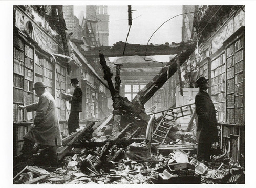 |
| The London Holland-House library after blitz german bombings. Picture taken on oct 1, 1940. |


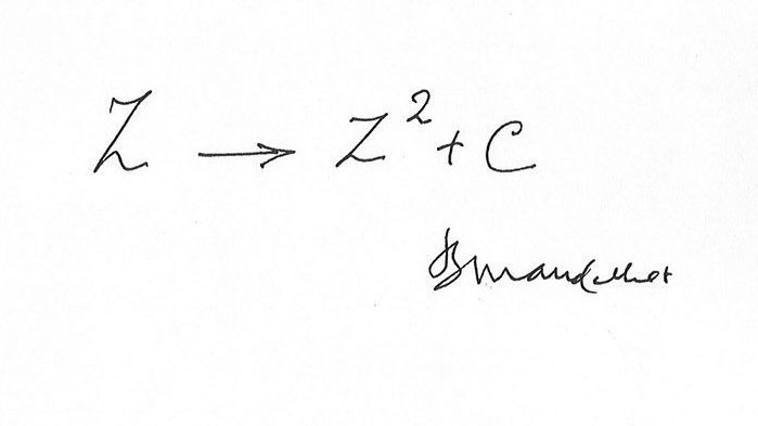

Where did Gandalf put his grey robes,
and his grey hat, after his fight with the Balrog?
Absolutes are easier to deal with than tradeoffs
But real beauty lies in between
In the nuances, in fractal dances
In chaotic indecisions, bouncing on spectre's ends
In misteriously misty shades of grey
In mutations, diversity, evolution
Be alive
Cast Doubt
Ready for change
Marco
(crossposted from ebmb)
.


ISO 11898-2 high speed
ISO 11898-2 is the most used physical layer standard for CAN networks. It describes the bus access unit (implemented as CAN high-speed transceiver) functions as well as some medium-dependent interface features.ISO 11898-3 (aka ISO 11519-2) defines the fault tolerant (and lower speed) CAN, up to 125Kbit/sec
In this standard the data rate is defined up to 1 Mbit/s with a theoretically possible bus length of 40 m at 1 Mbit/s. The high-speed standard specifies a two-wire differential bus whereby the number of nodes is limited by the electrical busload. The characteristic line impedance is 120 Ohm, the common mode voltage ranges from -2 V on CAN_L to +7 V on CAN_H. The nominal specific propagation delay of the two-wire bus line is specified at 5 ns/m. All these figures are valid only for a 1 Mbit/s transfer rate and a maximum network length of 40 m.
In order to achieve physical compatibility all nodes in the network must use the same or a similar bit-timing. For automotive applications the SAE published the SAE J2284 specification. For industrial and other non-automotive applications the system designer may use the CiA 102 recommendation. This specification defines the bit-timing for rates of 10 kbit/s to 1 Mbit/s. It also provides recommendations for bus lines and for connectors and pin assignment.
ISO 11898-3 fault-tolerant
An alternative form of bus interfacing and arrangement of bus lines is specified in ISO 11898-3 (fault-tolerant CAN). This standard is mainly used for body electronics in the automotive industry. Since for this specification a short network was assumed, the problem of signal reflection is not as important as for long bus lines. This makes the use of an open bus line possible.
This means low bus drivers can be used for networks with very low power consumption and the bus topology is no longer limited to a linear structure. It is possible to transmit data asymmetrically over just one bus line in case of an electrical failure of one of the bus lines.
ISO 11898-3 defines data rates up to 125 kbit/s with the maximum bus length depending on the data rate used and the busload. Up to 32 nodes per network are specified. The common mode voltage ranges between -2 V and +7 V. The power supply is defined at 5 V.
Transceiver chips, which support this standard, are available from several companies. The fault-tolerant transceivers support the complete error management including the detection of bus errors and automatic switching to asymmetrical signal transmission.
| Signal | recessive state | dominant state | unit | ||||
| min | nominal | max | min | nominal | max | ||
| CAN-High | 2.0 | 2.5 | 3.0 | 2.75 | 3.5 | 4.5 | Volt |
| CAN-Low | 2.0 | 2.5 | 3.0 | 0.5 | 1.5 | 2.25 | Volt |
| Signal | recessive state | dominant state | unit | ||||
| min | nominal | max | min | nominal | max | ||
| CAN-High | 1.6 | 1.75 | 1.9 | 3.85 | 4.0 | 5.0 | Volt |
| CAN-Low | 3.1 | 3.25 | 3.4 | 0 | 1.0 | 1.15 | Volt |
| Bus length (metres) | Maximum bit rate (bit/s) |
| 40 | 1 Mbit/s |
| 100 | 500 kbit/s |
| 200 | 250 kpit/s |
| 500 | 125 kbit/s |
| 6 km | 10 kbit/s |


"This SAE Recommended Practice provides the framework to allow reprogramming software applications from all vehicle manufacturers the flexibility to work with multiple vehicle data link interface tools from multiple tool suppliers. This system enables each vehicle manufacturer to control the programming sequence for electronic control units (ECU's) in their vehicles, but allows a single set of programming hardware and vehicle interface to be used to program modules for all vehicle manufacturers. This document does not limit the hardware possibilities for the connection between the PC used for the software application and the tool (e.g., RS-232, RS-485, USB, Ethernet...). Tool suppliers are free to choose the hardware interface appropriate for their tool. The goal of this document is to ensure that reprogramming software from any vehicle manufacturer is compatible with hardware supplied by any tool manufacturer. The U.S. Environmental Protection Agency (EPA) and the California Air Resources Board (ARB) have proposed requirements for reprogramming vehicles for all manufacturers by the aftermarket repair industry. This document is intended to meet those proposed requirements for 2004 model year vehicles. Additional requirements for the 2005 model year may require revision of this document, most notably the inclusion of SAE J1939 for some heavy-duty vehicles. This document will be reviewed for possible revision after those regulations are finalized and requirements are better understood. Possible revisions include SAE J1939 specific software and an alternate vehicle connector, but the basic hardware of an SAE J2534 interface device is expected to remain unchanged."Check also this article by Dan DeMaggio from Drew Technologies: http://www.drewtech.com/support/j2534/intro.html for the story of the development of this SAE recommendation.

The role of the Gateway (also known as the Data bus diagnostic interface J533) is the exchange of data between the CAN data bus systems (‘powertrain CAN data bus’, ‘convenience CAN data bus’ and ‘infotainment CAN data bus’) and the conversion of diagnostic data from CAN data bus systems to K-cable and vice versa so the data can be used by vehicle diagnosis, testing and information systems like the dealer VAS tools and Vagcom/VCDS.Here is a picture of the Volkswagen/Audi gateway (part no: 1K0907530AA), taken from http://www.my-gti.com/1101
For various reasons including power drain issues with third generation head units or the addition of new unsupported modules the CAN bus gateway must be upgraded to a newer revision. This guide covers the replacement of the CAN bus gateway in a 2005 MY06 Volkswagen Golf GTI. The upgrade replaces the 1K0 907 530 E (1K0907530E) with a 1K0 907 530 AA (1K0907530AA).

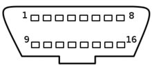
| Pin | SAE J1979, ISO 15031 | GM | Fiat | Opel | Saab | Isuzu | GM-LAN since 5.2002 |
|---|---|---|---|---|---|---|---|
| 1 | Manufacturer mandated | second UART | ABS, Brakes, K-Line | reserved | Saab Instruments (+) | SIR (GM8192 Prot.) | SW-LS-CAN (33kB) or DW-FT-CAN (+) (<125kB) |
| 2 | J1850 (+) PWM/VPW | J1850(+) VPW | DW-FT-CAN(+) | n/a | n/a | n/a | n/a |
| 3 | Manufacturer mandated | Comfort | Airbag | K-Line, K2, TCM, Sunroof, CDL, Multi-Timer | n/a | ABS (KW81-Prot.) | MS-CAN (+) (95kB) |
| 4 | Chassis ground | Chassis ground | Chassis ground | Chassis ground | Chassis ground | Chassis ground | Chassis ground |
| 5 | Signal ground | Signal ground | Signal ground | Signal ground | Signal ground | Signal ground | Signal ground |
| 6 | ISO 15765 HS-CAN (+) | PCM | ISO 15765 HS-CAN(+) | Blinkcode | Blinkcode | TCM | ISO 15765 HS-CAN (+) (500kB) |
| 7 | ISO 9141 K-Line | n/a | ISO 9141 K-Line (engine) | K-Line, K1 (engine) | K-Line, K1 (engine) | K-Linie, K1 (engine) | n/a |
| 8 | Manufacturer mandated | CCM | n/a | K-Line, K4 | K-Line (Saab 9000/1, KW81/82 Prot.) | n/a | reserved |
| 9 | Manufacturer mandated | first UART | Body ECU | reserviert | Saab Instruments (-) | ECM/TCM (GM8192 Prot.) | DW-FT-CAN (-) (<125kB) |
| 10 | J1850 (-) PWM | n/a | DW-FT-CAN (-) | n/a | n/a | n/a | n/a |
| 11 | Manufacturer mandated | EVA Controller | (Anti-Theft system) | reserved | L-Line Memory Seats | SIR | MS-CAN (-) (95kB) |
| 12 | Manufacturer mandated | ABS | engine compartment | K-Line, K3, ABS, TC, Steering, RTD, OW | n/a | ABS | K-Line (KW82 Prot.) |
| 13 | Manufacturer mandated | SIR | Luggage compartment | reserved f. K-Line, K5 | n/a | ECM | reserved |
| 14 | ISO 15765 HS-CAN (-) | E&C | ISO 15765 HS-CAN (-) | reserved | n/a | n/a | ISO 15765 HS-CAN (-) (500kB) |
| 15 | ISO 9141 L-Line | n/a | n/a | n/a | n/a | n/a | n/a |
| 16 | Battery Plus, unswitched | Battery Plus, unswitched | Battery Plus, unswitched | Battery Plus, unswitched | Battery Plus, unswitched | Battery Plus, unswitched | Battery Plus, unswitched |
An unshielded two-wire line (1) and (2) with a cross section of 0.35 mm² or 0.5 mm² is used for CAN bus wiring.On FIAT punto diesel, we found a CAN signal in the connector behind the radio. The CAN wires in this car are pink-black and pink-white.
The colour codes of the CAN bus wiring are:
Powertrain CAN high wire Orange/black
Convenience CAN high wire Orange/green
Infotainment CAN high Orange/violet
CAN low wire, (all) Orange/brown


But this impossibility is normally not due to physical reasons. Each ECU manufacturer uses its own set of rules & codes to craft data packets on their vehicles networks. These informations and data formats are not readily available, and there are no shared rules followed by different manufacturers.
Fm4200 is designed to be able to decode FMS CAN, which is a standard data format representation accepted and shared by all industrial vehicles (trucks). The target is to allow tachometer interconnect with vehicle dashboard.
Tachometers are devices that in many countries MUST be installed on trucks so to monitor driver behavior and work activities. Since there are many tachometer devices, which are built and installed by many countries certified suppliers, a standard was needed, so FMS was born. Non-professional access to tachometer data connection is generally prohibited.
Thru car databus reverse engineering techniques, mostly based on trial and error and/or leaked informations, it is theoretically possible to map some of the CAN data packets to their meanings. Generally read only approach is safe. But problems could arise when vehicle software maintenance is performed, because data packet meaning could change, and current manufacturers are not expected to openly disclose these details.
Write access to the drivetrain and engine bus is to be considered critical and is generally explicitely forbidden or strongly not recommended.
For sure it could be great if all the data was understandable and accessible, but there are important security implications if people irresponsibly tamper with these things. Vehicle security, insurance coverage and road safety could be impacted.
So, be careful and play always on the safe side.
My suggestion is to NEVER connect untrusted devices, unknown or potentially unreliable closed source software to critical systems.
Always study, learn and understand before playing. And always share responsibly your discoveries.
Best,
Marco