In this post I will report about my
experiences and studies about vehicle electronics.
Last edited on jun 27, 2012
CAVEATS: I found that the generally available informations about this subject on the internet is quite poor and not very clear. While I am trying to do my best in verifying, errors and mistakes could be present.
Please feel free to add your critics and comments.
This is going to be a long term project, so this page will be improved over time.
Cars are complex
Cars are getting complex. Car electronics is really sophisticated, and current cars have dozens of control units for managing devices, sensors, and actions.
ECUs: Elecronic Control Units
The Control Units talk on local vehicle networks, which are similar to a common computer LAN, but based on different protocols.
ECUs, Engine Control Units, were the first to be connected to vehicles network, soon followed by others ECUs (generic Electronic Control Units).
To reduce the amount of signal wires among the many electric components of a modern car, digital communication protocols were introduced, and digital electronic interfaces between every electric device and the communication infrastructure.
The most important ECU is the Engine Control Unit.
Here is a non-exaustive list of Engine Control Unit manufacturers for cars: BOSCH (example: EDC16), MAGNETI MARELLI (example: 95160), SAGEM (example: 95080), SIEMENS (example: TMS374).
Here is a PDF file from the chinese company
UIF Technology (a supplier of car electronics and diagnostic devices) with pictures of many Engine Control Units.
STANDARDS: a terrible headache
There are many standards defining protocols, signals, diagnostics.
Here is a probably incomplete and maybe wrong list
SAE and ISO are the most common standard and documents frameworks, but there are many others
SAE is the Society of Automotive Engineers.
SAE defines Communications Standard utilized in On-and Off-Road Land-Based Vehicles. In this schema 3 classes of communicating devices are explained:
CLASS A: up to 10Kbit/sec, multipurpose, asynchronous, used for non-realtime, smart sensors, wire reduction.
CLASS B: in the range 10Kbit/sec up to 125Kbit/sec, used for intermodule data transfer and non-realtime control. SAE J1850 is a CLASS B protocol, currently used for low-cost connectivity between nodes like instrumentation and diagnostic devices.
CLASS C: critical, high speed, realtime communications between device. For these needs, hi-speed CAN is currently used (up to 1Mbit/sec), but there are also faster alternatives, like
Flexray (up to 10Mbit/sec, firstly implemented in BMW
X7 X6 in 2008
see here).
SAE J1850 describes two different protocols: a low speed single wire VPW (Variable Pulse Width) protocol running at 10.4Kbit/sec and a faster two wire differential PWM (Pulse Width Modulation) protocol running at 41.6Kbit/sec. This is NOT CAN nor is it compatible with CAN.
VPW is classically used by GM (General Motors) vehicles.
PWM is classically used by Ford vehicles.
ISO_9141-2 is not a signaling protocol, but a diagnostic interface to check vehicle component functionality. It is a serial interface that runs at 9.6Kbit/sec. It is often available in OBD-2 connector.
ISO_11992 is a CAN bus used in trucks for communications between the tractor and the trailers.
SAE_J1939 is a set of specification based on an underlying CAN infrastructure, working with 29bit identifiers and usually with a bit rate of 250kbit/sec. This is normally used in trucks and industrial vehicles. It is a prerequisite for the FMS (see forward) system to work. An introduction to SAE_J1939 by Marcus Junger can be found on Vector site
here. Other J1939 infos are on
can-cia.org,. See also
here, and
here.
According to
wikipedia, SAE_J1939 supersedes SAE_J1708 and SAE_J1587.
Here is a list of Automotive data buses, by Leroy Davis.
Vehicle Networks
Actually there are many vehicle networks, eventually based on different standards, different criticality, different protocols, and different communication speeds. Currently these networks are converging to the CAN standard, but there are many others. Since CAN is now the de-facto standard for vehicle networking, sometimes it is also identified as VDB (Vehicle Data Bus).
Despite its popularity, CAN bus is not the only network inside any modern vehicle, and in a single vehicle there are usually different networks (multiple CAN networks and NON-CAN networks).
CAN
CAN stands for
Controller Area Network. It was originally developed by Bosch, starting in 1983. CAN is used in many automation environments and not only in automotive industry.
In a CAN bus all the communicating devices are connected to the same two wires, labeled CAN-High and CAN-Low. All the devices must use the bus at the same speed. At each end, the two wires are connected with a 120 ohm termination resistor. It is not required to have a common ground signal among the communicating devices. Bus maximum length is dependent from the operational speed, and at 1Mbit/sec is about 40m. Vehicle network bus speeds are usually below 500Kbit/sec. High speed bus vehicle implementation often adopt twisted pair wires.
In a normal situation, the two wires carry a two-level signal, perfectly specular, and whenever one is high the other is low. Here are two nice pictures (source:
picoauto.com ) representing oscilloscope reading of the two wires of a CAN bus. The second image allow a clear understanding of the specular nature of the signals.
From these pictures, the different logical values of the signals can be read, and here each signal has a span of about 1V. In the upper picture, a full CAN packet transfer is visible. The overall packet transfer time is about 200ms (320-120).
Actual CAN bus voltages are not usually this neat.
Here is an actual example (this too from
picoauto) (Voltage references seem nonsensical in this picture).
The CAN Protocol
Currently there are two main version of the CAN protocol
Standard CAN: 2.0A with 11bits identifiers
Extended CAN: 2.0B with 29bits identifiers
CAN is defined in ISO_11519 and ISO_11898.
ISO 11898-2 defines the high speed CAN, up to 1Mbit/sec
ISO 11898-2 high speed
ISO 11898-2 is the most used physical layer standard for CAN networks. It describes the bus access unit (implemented as CAN high-speed transceiver) functions as well as some medium-dependent interface features.
In this standard the data rate is defined up to 1 Mbit/s with a theoretically possible bus length of 40 m at 1 Mbit/s. The high-speed standard specifies a two-wire differential bus whereby the number of nodes is limited by the electrical busload. The characteristic line impedance is 120 Ohm, the common mode voltage ranges from -2 V on CAN_L to +7 V on CAN_H. The nominal specific propagation delay of the two-wire bus line is specified at 5 ns/m. All these figures are valid only for a 1 Mbit/s transfer rate and a maximum network length of 40 m.
In order to achieve physical compatibility all nodes in the network must use the same or a similar bit-timing. For automotive applications the SAE published the SAE J2284 specification. For industrial and other non-automotive applications the system designer may use the CiA 102 recommendation. This specification defines the bit-timing for rates of 10 kbit/s to 1 Mbit/s. It also provides recommendations for bus lines and for connectors and pin assignment.
ISO 11898-3 (aka ISO 11519-2) defines the fault tolerant (and lower speed) CAN, up to 125Kbit/sec
ISO 11898-3 fault-tolerant
An alternative form of bus interfacing and arrangement of bus lines is specified in ISO 11898-3 (fault-tolerant CAN). This standard is mainly used for body electronics in the automotive industry. Since for this specification a short network was assumed, the problem of signal reflection is not as important as for long bus lines. This makes the use of an open bus line possible.
This means low bus drivers can be used for networks with very low power consumption and the bus topology is no longer limited to a linear structure. It is possible to transmit data asymmetrically over just one bus line in case of an electrical failure of one of the bus lines.
ISO 11898-3 defines data rates up to 125 kbit/s with the maximum bus length depending on the data rate used and the busload. Up to 32 nodes per network are specified. The common mode voltage ranges between -2 V and +7 V. The power supply is defined at 5 V.
Transceiver chips, which support this standard, are available from several companies. The fault-tolerant transceivers support the complete error management including the detection of bus errors and automatic switching to asymmetrical signal transmission.
The preceding two quotes of text about CAN physical layer specifications are taken from here (fetched on dec 4 2010):
http://www.can-cia.org/index.php?id=517
Also there are other physical layer standards.
The following section is shamelessly copied from Staffan Nilsson
web page
(with some corrections)
-----------------------
ISO 11898-2 voltage levels (CAN High Speed)
| Signal | | recessive state | | | dominant state | | unit |
| min | nominal | max | min | nominal | max | |
| CAN-High | 2.0 | 2.5 | 3.0 | 2.75 | 3.5 | 4.5 | Volt |
| CAN-Low | 2.0 | 2.5 | 3.0 | 0.5 | 1.5 | 2.25 | Volt |
Note that for the recessive state, nominal voltage for the two wires is the same. This decreases the power drawn from the nodes through the termination resistors. These resistors are 120ohm and are located on each end of the wires. Some people have played with using central termination resistors (that is, putting them in one place on the bus). This is not recommended, since that configuration will not prevent reflection problems.
ISO 11519 voltage levels (CAN Low Speed)
| Signal | | recessive state | | | dominant state | | unit |
| min | nominal | max | min | nominal | max | |
| CAN-High | 1.6 | 1.75 | 1.9 | 3.85 | 4.0 | 5.0 | Volt |
| CAN-Low | 3.1 | 3.25 | 3.4 | 0 | 1.0 | 1.15 | Volt |
ISO 11519 does not require termination resistors. They are not necessary because the limited bit rates (maximum 125 kB/s) makes the bus insensitive to reflections. The voltage level on the CAN bus is recessive when the bus is idle.
Bus lengths
The maximum bus length for a CAN network depends on the bit rate used. It is required that the wave front of the bit signal has time to travel to the most remote node and back again before the bit is sampled. This means that if the bus length is near the maximum for the bit rate used, one should
choose the sampling point with utmost care - one the other hand, one should always do that!
Below is a table of different bus lengths and the corresponding maximum bit rates.
| Bus length (metres) | Maximum bit rate (bit/s) |
| 40 | 1 Mbit/s |
| 100 | 500 kbit/s |
| 200 | 250 kpit/s |
| 500 | 125 kbit/s |
| 6 km | 10 kbit/s |
Cables
According to the ISO 11898 standard, the impedance of the cable shall be 120 +- 12 ohms. It should be twisted pair, shielded or unshielded. Work is in progress on the single-wire standard SAE J2411.
-----------------------
CAN frames
Here are some informations about CAN data frames
the following picture is from http://www.jcelectronica.com/articles/CAN%20bus%20tutorial_2.htm
The Standard and Extended frames are shown, and the different address field length can be seen.
CAN reliability
CAN bus communications are usually very reliable, quite insensitive to external interferences (since external interferences affect similarly
both wires, the difference between the voltages remains unchanged), and to single control unit fault. The devices can often work even in case of bus being severely miswired (one cable shorted to ground or to vcc). No need of a common ground also increases robustness. This reliability is among the properties that made it the current standard in difficult environments, with wide temperature ranges, and very varying environmental situations.
Detecting CAN
Since there are many wires, it is not easy to identify the proper ones.
0.CAN signals are usually not present if the key is not turned to power the dashboard. (It is normally not needed that the engine is powered).
1.CAN wires are usually twisted.
2.Checking CAN signal presence without the use of an oscilloscope: A simple test to see if the bus is operating correctly is to use a multimeter and measure the voltage between the two wires. In "perfect" situations, if the bus is active and working it will show a steady 2.5V or 0,5V (in absence of signal changes), or a quick alternance between 0,5 and 2,5V. If not working it will be 0V as one of the CAN controllers on the network is pulling the bus low (known as Bus Off).
3. Operating with a two channels oscilloscope, and using the subtract function between the two signals CAN-H and CAN-L, you should get a constant (because the two signals have opposite phases). Oscilloscope can also help in detecting the speed of the CAN bus signals. (will add details here).
4. An indirect CAN presence indicator could be testing for proper termination. Proper termination of a CAN bus can be easily tested with a multimeter: when the bus is not used, a resistance of 60ohm should be measured between the two cables (the two 120 ohms terminators in parallel at each side give a global resistance of 120/2=60 ohms).
5. As a useful tool for CAN detection check the Würth
CANfinder device.
6. CAN signals could not be present where they should be (i.e. in the OBD2 connector) if a proper setting is not performed on the gateway device.
Interfacing with CAN
In term of circuitry, every device connecting to CAN bus usually interfaces via a
CAN Controller, which in turn acceses the bus via a
CAN line driver (actually a transceiver).
The CAN controller actually speaks with the device in some way (for example via a serial RS232 interface) and on the other Many manufacturers produce CAN line driver integrated circuits, for example Dallas Semiconductors/MAXIM
MAX13050 or Microchip
MCP2551.or Philips
PCA82C250. or Philips/NXP
TJA1054
The following picture shows a generic CAN bus with some devices connected. Proper bus termination should be present at each bus end to damp electric signal reflection (echos). Also it is important to minimize length of the connection between the bus and the transceiver of each connected device (for minimizing undesired echo effects).
Modules are sets of ECUs
In a vehicle, a
Module usually identifies a set of two or more Electronic Control Units.
Engine control being the first and most critical, the corresponding Control Units are the most complex.
Engine Control Unit (ECU) is supported by
Transmission Control Unit (TCU) and the two are sometimes referred as
Powertrain Control Module (PCM). Transmission Control Unit, among other things, takes care of gear shift.
User related Electronic Control Units are often referred as a whole with the term
Body Control Module or BCM .
Different Networks
The different criticality of the signaling among the vehicle electronic devices, created a push for insulating the networks of different modules, for security needs, but also due to different equipment interfaces being at different speeds.
These different networks are grouped in 3 main classes:
- Body Frame, requiring speeds up to 10Kbps (electric glasses, doors, etc,) [as example of BCM see later references to Peugeot BSI Built-in System Interface]
- Dashboard instrumentation, requiring speed range 50-125Kbps (instrumentation, air conditioning, etc.)
- Engine and powertrain, requiring high speed (up to 1Mbps)
Some of these vehicle networks can also be non-CAN. There are other standards used in vehicle networks, like
LIN (used for low cost, low speed, non critical use, see also
here),
FlexRay (used for high speed, critical needs, in BMW SUVs),
MOST (Media Oriented System Transport) for multimedia and infotainment.
Bus Separation
Engine Control, Airbag, Braking subsystem, Speed control and ABS, are the most safety-critical systems, require high speed, and therefore are usually kept separated from less critical systems.
The separation between the different CAN buses allow much more resilience of the critical systems in the case a noncritical control unit fails (the car engine still starts if you have a problem in the cd-player or in the cabin lights).
Gateways between different networks
In most vehicles, many CAN networks are there, operating at different speed, and that there are
gateways allowing data being transferred among the different buses.
The presence of these gateways allow filtered transfer of information, along with eventual speed change. A gateway could act as a firewall allowing only the propagation of specific packets. Gateways are actually electronic devices connected to more than one bus, and can be programmed to allow packet filtering.
There is a interesting specification called Pass-Through SAE J2534-1 which is designed to allow a sort of common protocol (!!vendor and brand independent!!) for traversing in-between bus gateways (
CAN and not CAN). This standard should be supported on all vehicles manufactured after 2004. Pass-through specification is targeted to reprogramming and re-flashing of individual electronic control units, but allows also read and write I/O, and periodic messages definition. There is also a set of defined APIs (Application to Program Interfaces) thru which the dialogue can be implemented.
Here is the description of the SAE J2534-1 recommendation document, as taken from
http://standards.sae.org/j2534/1_200412/ on sept 22, 2011.
"This SAE Recommended Practice provides the framework to allow reprogramming software applications from all vehicle manufacturers the flexibility to work with multiple vehicle data link interface tools from multiple tool suppliers. This system enables each vehicle manufacturer to control the programming sequence for electronic control units (ECU's) in their vehicles, but allows a single set of programming hardware and vehicle interface to be used to program modules for all vehicle manufacturers. This document does not limit the hardware possibilities for the connection between the PC used for the software application and the tool (e.g., RS-232, RS-485, USB, Ethernet...). Tool suppliers are free to choose the hardware interface appropriate for their tool. The goal of this document is to ensure that reprogramming software from any vehicle manufacturer is compatible with hardware supplied by any tool manufacturer. The U.S. Environmental Protection Agency (EPA) and the California Air Resources Board (ARB) have proposed requirements for reprogramming vehicles for all manufacturers by the aftermarket repair industry. This document is intended to meet those proposed requirements for 2004 model year vehicles. Additional requirements for the 2005 model year may require revision of this document, most notably the inclusion of SAE J1939 for some heavy-duty vehicles. This document will be reviewed for possible revision after those regulations are finalized and requirements are better understood. Possible revisions include SAE J1939 specific software and an alternate vehicle connector, but the basic hardware of an SAE J2534 interface device is expected to remain unchanged."
Check also this article by Dan DeMaggio from
Drew Technologies:
http://www.drewtech.com/support/j2534/intro.html for the story of the development of this SAE recommendation.
Here is an example of a CAN bus dual interface gateway device: the CAN/CAN Gateway CG-ARM7, manufactured by EMS Dr. Thomas Wünsche:
http://www.ems-wuensche.com/?menu=_prod&cont=datasheets/html/cgarm7_e
Such a device is indeed a firewall with sophisticated packet content filtering and rewriting capacity.
Here is a document describing a CAN gateway device in a Volkswagen Golf car
The following two paragraphs are taken from
http://www.my-gti.com/2296
The role of the Gateway (also known as the Data bus diagnostic interface J533) is the exchange of data between the CAN data bus systems (‘powertrain CAN data bus’, ‘convenience CAN data bus’ and ‘infotainment CAN data bus’) and the conversion of diagnostic data from CAN data bus systems to K-cable and vice versa so the data can be used by vehicle diagnosis, testing and information systems like the dealer VAS tools and Vagcom/VCDS.
For various reasons including power drain issues with third generation head units or the addition of new unsupported modules the CAN bus gateway must be upgraded to a newer revision. This guide covers the replacement of the CAN bus gateway in a 2005 MY06 Volkswagen Golf GTI. The upgrade replaces the 1K0 907 530 E (1K0907530E) with a 1K0 907 530 AA (1K0907530AA).
Here is a picture of the Volkswagen/Audi gateway (part no: 1K0907530AA), taken from
http://www.my-gti.com/1101
This gateway in Volkswagen terms is called "Data bus diagnostic interface J533". It is used in many car models from this vendor. I found an Audi technical document (from Audi A5 owners group website
Audi_A5_-_Networking_en_2.pdf) describing the 4 different version of this gateway component (differences are in terms of its interfaces), for different car models. It is connected to many different buses (different CANs, LIN, MOST). The document states that the "transport mode" can be activated on demand. I guess that this transport mode could allow flow of information between the different buses thru the gateway itself (that in this mode acts somewhat like a router).
Check also this
webpage about J533 gateway.
OBD: On Board Diagnostic
Due to the progressive diffusion of electronic devices in the vehicle industry, also diagnostic procedures started to rely on querying these different pieces of electronics, for troubleshooting, and parameter tuning.
The
On Board Diagnostic (OBD) standards define how these diagnosis can be performed. Each Control Unit has a set of
Diagnostic Trouble Codes (DTC) that can help in identifying its status or eventual failures.
Actual diagnosis is performed by a technician connecting a probing device to a specific plug inside the vehicle, and performing analysis.
In many vehicles, the OBD connector (currently usually compliant to OBD-2 standard) is within reach from the driver seat, and allows access to at least one of the vehicle CAN buses.
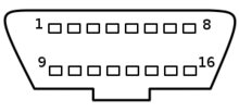
Over the years, many different versions of the OBD standard appeared, and the most current one is labeled OBD-2 or OBD-II, which uses a female 16-pin (2x8) SAE J1962 connector on the vehicle. Here is the pinout of its female connector (from
wikipedia).
Specific gateway configurations could be needed so to allow specific Electronic Control Units traffic (filtering) to be available on the OBD-2 CAN interface. Also, depending on the manufacturer and model, CAN bus availability on the OBD-2 connector could require a specific configuration elsewhere (maybe jumpers in the circuit breaker panel).
Being present in many vehicles, the OBD-2 connector usually allows access to many diagnostic signals. Sometimes more than one CAN bus is made available on the connector, on different pins.
Here is the pinout of the FIAT OBD-2 connector:
http://pinoutsguide.com/CarElectronics/fiat_car_obd_ii_pinout.shtml
Some "rules" about the OBD-2 connector
(info from
http://www.auterraweb.com/obdiipinout.html and
http://www.obd-ii.de/tech_conn.html )
If pin 5,6,14,16 are connected, the pins 6 and 14 are CAN-HI/LOW (ISO_15765-4 / SAE_J2284), while pin 5 is ground and pin 16 is 12Vcc
If pins 5,7,16 and optionally 15 are connected, the connector supports access to ISO_9141-2 (aka KWP): pin 5 is ground, pin 16 is 12Vcc, pin 7 is ISO-data (aka ISO_K-line), as well as optional pin 15 which is older ISO_9141-2 (aka ISO_L-line).
If pins 2,5,16 are connected, the connector supports access to VPW_J1850: pin 5 is ground, pin 16 is 12Vcc, and pin 2 is VPW-data
If pins 2,5,10,16 are connected, the connector supports access to PWM_J1850: pin 5 is ground, pin 16 is 12Vcc, and pin 2 and 10 are PWM-data
Connector Pins 1,3,8,9,11,12,13 (if connected) are used differently from different vehicle manufacturers, and the OBD-2 standard does not define their role.
Contact usage of some manufacturers (table from http://www.obd-ii.de/tech_conn.html)
:
| Pin | SAE J1979,
ISO 15031 | GM | Fiat | Opel | Saab | Isuzu | GM-LAN
since 5.2002 |
|---|
| 1 | Manufacturer mandated | second UART | ABS, Brakes, K-Line | reserved | Saab Instruments (+) | SIR (GM8192 Prot.) | SW-LS-CAN (33kB)
or
DW-FT-CAN (+) (<125kB) |
| 2 | J1850 (+) PWM/VPW | J1850(+) VPW | DW-FT-CAN(+) | n/a | n/a | n/a | n/a |
| 3 | Manufacturer mandated | Comfort | Airbag | K-Line, K2, TCM, Sunroof, CDL, Multi-Timer | n/a | ABS (KW81-Prot.) | MS-CAN (+) (95kB) |
| 4 | Chassis ground | Chassis ground | Chassis ground | Chassis ground | Chassis ground | Chassis ground | Chassis ground |
| 5 | Signal ground | Signal ground | Signal ground | Signal ground | Signal ground | Signal ground | Signal ground |
| 6 | ISO 15765 HS-CAN (+) | PCM | ISO 15765 HS-CAN(+) | Blinkcode | Blinkcode | TCM | ISO 15765 HS-CAN (+) (500kB) |
| 7 | ISO 9141 K-Line | n/a | ISO 9141 K-Line (engine) | K-Line, K1 (engine) | K-Line, K1 (engine) | K-Linie, K1 (engine) | n/a |
| 8 | Manufacturer mandated | CCM | n/a | K-Line, K4 | K-Line (Saab 9000/1, KW81/82 Prot.) | n/a | reserved |
| 9 | Manufacturer mandated | first UART | Body ECU | reserviert | Saab Instruments (-) | ECM/TCM (GM8192 Prot.) | DW-FT-CAN (-) (<125kB) |
| 10 | J1850 (-) PWM | n/a | DW-FT-CAN (-) | n/a | n/a | n/a | n/a |
| 11 | Manufacturer mandated | EVA Controller | (Anti-Theft system) | reserved | L-Line Memory Seats | SIR | MS-CAN (-) (95kB) |
| 12 | Manufacturer mandated | ABS | engine compartment | K-Line, K3, ABS, TC, Steering, RTD, OW | n/a | ABS | K-Line (KW82 Prot.) |
| 13 | Manufacturer mandated | SIR | Luggage compartment | reserved f. K-Line, K5 | n/a | ECM | reserved |
| 14 | ISO 15765 HS-CAN (-) | E&C | ISO 15765 HS-CAN (-) | reserved | n/a | n/a | ISO 15765 HS-CAN (-) (500kB) |
| 15 | ISO 9141 L-Line | n/a | n/a | n/a | n/a | n/a | n/a |
| 16 | Battery Plus, unswitched | Battery Plus, unswitched | Battery Plus, unswitched | Battery Plus, unswitched | Battery Plus, unswitched | Battery Plus, unswitched | Battery Plus, unswitched |
Accessing CAN bus in cars
When CAN bus is not available in the OBD2 plug or it is not feasible to connect to that plug, or if the gateway is not "publishing" the CAN signals on the OBD2 port, the bus can be accessed simply connecting to its wires.
But a disclaimer is needed:
In most cases, car manufacturers are not disclosing the specifications of their diagnostic systems and there are no easy approaches that are consistant across the different brands. Even if you are able to access CAN signals, it will not an easy task to decode and understand the meaning of the data packets.
Here is a guide (prepared by uk company
Racelogic) in finding the right wires in different vehicles. Devices like the aforementioned Würth
canfinder can also be useful.
On Volkswagen Golf cars, the following wire color codes apply (from
http://www.my-gti.com/991/performing-repairs-on-can-bus-wiring ). All the three CAN networks use cable pairs, and each pair can be identified by the color of the CAN-HIGH wire, being all the CAN-LOW wires of the same color.
An unshielded two-wire line (1) and (2) with a cross section of 0.35 mm² or 0.5 mm² is used for CAN bus wiring.
The colour codes of the CAN bus wiring are:
Powertrain CAN high wire Orange/black
Convenience CAN high wire Orange/green
Infotainment CAN high Orange/violet
CAN low wire, (all) Orange/brown
On FIAT punto diesel, we found a CAN signal in the connector behind the radio. The CAN wires in this car are pink-black and pink-white.
the following link describes a project to interface a car CAN bus to a wifi network:
http://www2.cs.uidaho.edu/~oman/RTCS/Wood-Chroninger-project.pptx
For Peugeot (/PSA and probably for cytroen) cars, check this site:
http://peugeot.mainspot.net/ where you can find accurate information and Complete Wiring diagram for
Peugeot307, along with information about BSI (Body Control:
Built-in
System
Interface)
Peugeot BSI is connected and "coupled" to Engine Control Unit, and there are protections to avoid tampering by non official dealers or auto-repair technicians. Here are a set of warnings related to Peugeot BSI-ECU maintenance:
http://www.liontamer.net/forums/index.php/topic,3.0.html
Here is a picture of a Peugeot BSI.
Peugeot/PSA cars used to implement their own version of CAN bus, called VAN (Vehicle Area Network Comfort data VAN bus / Body Control Data bus). I found some clever guys who did some awesome job in collecting information about VAN: Graham Auld, and Alessandro Zummo. Check
http://graham.auld.me.uk/projects/vanbus/index.html and
http://code.google.com/p/van-bus/ I got to these sites via
this webpage.
Accessing CAN in trucks
Specifically for trucks, there is another standard, to have a uniform access to vehicle data, and targeted for the needs of driving monitoring devices.
This FMS (Fleet Management System) standard is very important for allowing access to specific truck information like the tachometer and odometer, which are needed to be read in the devices to control the driver activity (digital tachographs). FMS requires a SAE J1939 CAN 29-bit 250kbit/sec underlying standard.
For european digital tachographs, check
http://www.dtco.vdo.com
In order to be compliant with FMS standard, truck manufacturers implement a specific gateway ECU which reads the informations required by the standard from all the suitable places and thru all the required standard, complying with internal vehicle-brand-specific protocols, and makes all these informations available thru a specific CAN bus to which the tachometer device is connected.
In this way, an FMS compliant digital tachometer devices can be easily connected to any FMS compliant truck.
Different connection cables
(this section needs work and it is partially outdated by what I wrote in the OBD-2 connector section)
A number of different ready made cables exist to access car diagnostics, usually via the aforementioned ODB-2 connector
here is a list of their names, but I am far from understanding their differences
SAE J1850 (can be a dual wire differential 41.6 Kbit/s PWM -Pulse Width Modulation-, or a 10.4Kbit/s VPW singlewire -Variable Pulse Width- ). see
this intel document.
SAE J2534 (this is a PWM protocol used in Ford, Lincoln, Mercury, Mazda vehicles)
K-LINE and L-LINE (ISO 9141-2) (to be explained: i need to study)
ISO 14230-4 (also known as KWP)
PWM CAN
HS-CAN (iso 15765)
VAG-COM is not a cable, but a product by Ross-Tech. It is a diagnostic windows software for Volkswagen/Audi. Some cables to be used with this software are labeled VAG-COM
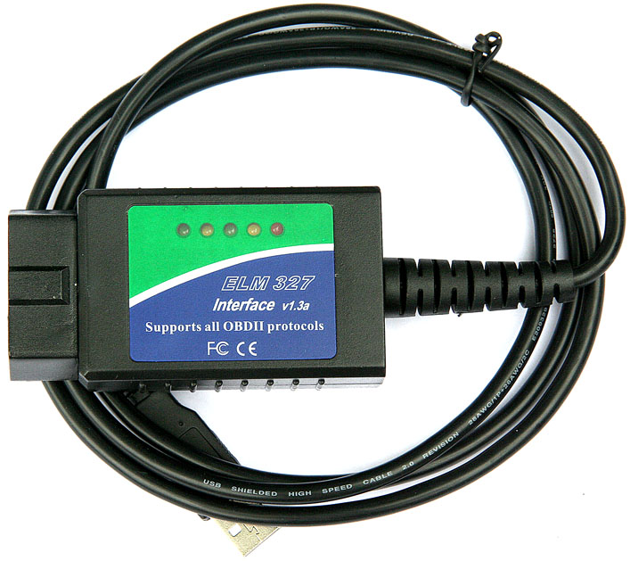
ELM 32x are integrated circuits, (here is
elm327 description), sold by
elmelectronics.com and based on
Microchip Technology Inc. raw devices. These ELM chips act as generic ODB2 decoders and are able to identify and decode many of the different signals available on the ODB2 plug, converting them to RS232, suitable for connection to a PC. Many different PC diagnostic software are capable of interfacing with car electronics via an ELM based adaptor, like
this
(To Be fixed)
Arduino and CAN
It is possible to interface an Arduino 2009 board with CAN bus, via a specific CAN shield
I successfully used
SkPang Arduino CAN-Bus Shield, to connect to an Audi A6 (2003) and I was able (using the provided sample application) to successfully read RPM (revolutions per minute) data from the engine using a polling mechanism.
This shield uses a
MCP2515 CAN controller and a
MCP2551 CAN line driver.
Here is a typical configuration of MCP2551
We are currently working on improving the code provided with the shield so to have more sophisticated functions.
Oct 2011 Note: As Rick (in an anonymous comment) said, Sk-Pang shield uses a library taken from Fabien Greif code ( here is the main site:
http://www.kreatives-chaos.com/artikel/universelle-can-bibliothek ).The code can be improved, and I hope I will have some time to dedicate to this.
OBDuino
This is a project, started in 2009, to use a custom Arduino-like board to interface to car CAN-Bus and build a
The project is described in this wikipedia page:
http://en.wikipedia.org/wiki/OBDuino and the code repository, along with some pictures of prototypes, is in a google-code page, here:
http://code.google.com/p/opengauge/wiki/OBDuinoInterface
MPGuino
This project is targeted to build a fuel measurement computer, with an Arduino like device, analyzing the impulses to the fuel injectors, and having tables for calculating the specific fuel injected basing on impulse duration. The signals have to be directly read/taken from the main engine ECU connections to the fuel injectors. Data appears extremely accurate. Here is the link:
http://ecomodder.com/wiki/index.php/MPGuino
Teltonika FM4200
This is a device specifically designed to interface with FMS CAN interface in trucks.
I am also testing
this device, which uses a NXP LPC2368 microcontroller which is (incidentally) the same uc used by the
mbed project.
Here is some info about the microcontroller which includes a CAN controller (but not a CAN transceiver). The FM4200 circuits utilizes a Texas Instruments
SN65HVD234D 3.3V CAN transceiver. I will write more about this device, as soon as I will have performed more thoroughful tests.
CAN Bus data reverse engineering:
For a Toyota Prius car, by Attila Vass:
http://www.vassfamily.net/ToyotaPrius/CAN/cindex.html
For a SAAB car by Tomi Liljemark:
http://pikkupossu.1g.fi/tomi/projects/i-bus/i-bus.html
General References and links
The great CAN-CIA site:
http://www.can-cia.org/ which is probably the best and more reliable reference site available.
The
CAN dictionary: contains a definition of most of the acronyms and abbreviations.
Staffan Nilsson's great page about CAN:
http://www.staffannilsson.eu/developer/CAN.htm
Bosch CAN 2.0
specifications.
Mike J Schofield pages: (non working url:
http://www.mjschofield.com/ - there is a mirror in Staffan Nilsson site)
http://www.ixxat.com/can-controller-area-network-introduction_en.html
http://www.jcelectronica.com/articles/CAN%20bus%20tutorial.htm
CAN analysis and equipment vendors
http://www.vector-group.net
http://www.kvaser.com
http://www.ems-wuensche.com : I bought an EMS-Wuensche CPC-USB/ARM7 with galvanic optoinsulation and lowspeed transceiver (TJA1054) for automotive. Received the object (2010.dec.10), and first impression is good: seems very well built and reliable. Will soon test it on the field.
http://www.lawicel.com/
http://www.peak-system.com/
CAN bus in motorcycles
Of course, also motorcycles electronic utilizes digital protocols.
Here is a page about CAN bus in BMW motorcycles.
An affordable and cheap Oscilloscope
Actually I ordered this
Rigol DS1052E,
but I am still waiting the device to arrive.
Will be able to report on its features, as soon as I evaluate it.
Here are informations about the scope:
http://marco.guardigli.it/2011/02/rigol-ds1052e-oscilloscope.html
Software
FreeDiag:
http://freediag.sourceforge.net/
FiatECUScan is a software for analyzing Italian made cars (fiat/alfa/lancia branded). Comes in free version and in paid version, with different features.
http://fiatecuscan.net. Here is a
list of the vehicles supported by current version of FiatECUScan.
FAQ: Q&A
Here are some questions I received by email and the answers I sent.
Q: Is it possible to read value of XXX connecting to the can bus of my car?
A:
As quick answer I would just say that it is not possible.
But this impossibility is normally not due to physical reasons. Each ECU manufacturer uses its own set of rules & codes to craft data packets on their vehicles networks. These informations and data formats are not readily available, and there are no shared rules followed by different manufacturers.
Fm4200 is designed to be able to decode FMS CAN, which is a standard data format representation accepted and shared by all industrial vehicles (trucks). The target is to allow tachometer interconnect with vehicle dashboard.
Tachometers are devices that in many countries MUST be installed on trucks so to monitor driver behavior and work activities. Since there are many tachometer devices, which are built and installed by many countries certified suppliers, a standard was needed, so FMS was born. Non-professional access to tachometer data connection is generally prohibited.
Thru car databus reverse engineering techniques, mostly based on trial and error and/or leaked informations, it is theoretically possible to map some of the CAN data packets to their meanings. Generally read only approach is safe. But problems could arise when vehicle software maintenance is performed, because data packet meaning could change, and current manufacturers are not expected to openly disclose these details.
Write access to the drivetrain and engine bus is to be considered critical and is generally explicitely forbidden or strongly not recommended.
For sure it could be great if all the data was understandable and accessible, but there are important security implications if people irresponsibly tamper with these things. Vehicle security, insurance coverage and road safety could be impacted.
So, be careful and play always on the safe side.
My suggestion is to NEVER connect untrusted devices, unknown or potentially unreliable closed source software to critical systems.
Always study, learn and understand before playing. And always share responsibly your discoveries.
Best,
Marco
------
Marco (@mgua on Twitter)
.