Family has a new member: miss purr. She was born on sept 22 2010.
She had a brother who unfortunately died at birth.
isn't she cute?
Here are some new pictures, taken some weeks later:
.
Tuesday, September 28, 2010
Sunday, September 12, 2010
Smile and be happy
Here is one of the nicest clip I ever found on youtube
"Validation" is a fable about the magic of free parking.
Starring TJ Thyne & Vicki Davis.
Writer/Director/Composer - Kurt Kuenne.
Awards:
Winner - Best Narrative Short, Cleveland Int'l Film Festival,
Winner - Jury Award, Gen Art Chicago Film Festival,
Winner - Audience Award, Hawaii Int'l Film Festival,
Winner - Best Short Comedy, Breckenridge Festival of Film,
Winner - Crystal Heart Award, Best Short Film & Audience Award, Heartland Film Festival,
Winner - Christopher & Dana Reeve Audience Award, Williamstown Film Festival,
Winner - Best Comedy, Dam Short Film Festival,
Winner - Best Short Film, Sedona Int'l Film Festival.
I like the idea and the music, and the actors.
I smiled.
Did you?
marco (@mgua on twitter)
.
"Validation" is a fable about the magic of free parking.
Starring TJ Thyne & Vicki Davis.
Writer/Director/Composer - Kurt Kuenne.
Awards:
Winner - Best Narrative Short, Cleveland Int'l Film Festival,
Winner - Jury Award, Gen Art Chicago Film Festival,
Winner - Audience Award, Hawaii Int'l Film Festival,
Winner - Best Short Comedy, Breckenridge Festival of Film,
Winner - Crystal Heart Award, Best Short Film & Audience Award, Heartland Film Festival,
Winner - Christopher & Dana Reeve Audience Award, Williamstown Film Festival,
Winner - Best Comedy, Dam Short Film Festival,
Winner - Best Short Film, Sedona Int'l Film Festival.
I like the idea and the music, and the actors.
I smiled.
Did you?
marco (@mgua on twitter)
.
Wednesday, September 1, 2010
Hitec Aurora9
I received my new Aurora 9 RC transmitter yesterday, and I am very excited about its features.
I am a long time owner of Hitec Optic 6 and before buying the Aurora9 I was evaluating also the Futaba T10CG. The Futaba was more expensive, and also more common in my local group of RC modelers, but is lacking the telemetry features that are very interesting for me.
In the coming weekend I will test it on the fly field.
My new Aurora has firmware release 1.06, as seen from the info menu of the system panel.
I also ordered HPP-22 device for connecting radio to pc and also the HTS-SS Sensor Station, but these components are still to arrive.
First Impressions
I found the device extremely easy to setup. There is a great wizard for setting up all the model features. It is really easy and quick. Great improvement over the Optic 6 menus that I found quite clumsy and not intuitive.
Radio pairing is straightforward. Touch Screen is simply great. Screen is large and allows quick check of all the trim settings. Subtrims and EPAs (End Of Paths)are just two taps away.
It would be nice to have some front indicators of the state of the two leds on the Spectra AFHSS module. Those leds on the back are simply impossible to check while piloting.
Telemetry!
I am excited about its telemetry features, and I am planning to study the protocol used between the sensors and the receiver. I think it could be an I2C protocol. Will definitely try to find some more information.
The basic idea would be to decode the protocol so to add my own sensors on the plane, and to send to the pilot the collected data via the receiver data port thru the downlink channel.
I want a Datalogger!
My idea is to build a small datalogging interface device to be used at fly field, to be connected to the data port of the spectra AFHSS module, so to log telemetry data to flash memory.
The flash memory could then be read on the pc.
I think that such a project could be very useful for Hitec Aurora9 users, and eventually for other telemetry capable radio systems..
Links:
About reverse engineering of HPP-22: http://www.rcgroups.com/forums/showthread.php?t=1174742
Telemetry forum on RC Model Reviews: http://rcmodelreviews.com/forum/viewforum.php?f=46
Will keep this post up to date with my new discoveries...
Marco (@mgua on twitter)
.
I am a long time owner of Hitec Optic 6 and before buying the Aurora9 I was evaluating also the Futaba T10CG. The Futaba was more expensive, and also more common in my local group of RC modelers, but is lacking the telemetry features that are very interesting for me.
In the coming weekend I will test it on the fly field.
My new Aurora has firmware release 1.06, as seen from the info menu of the system panel.
I also ordered HPP-22 device for connecting radio to pc and also the HTS-SS Sensor Station, but these components are still to arrive.
First Impressions
I found the device extremely easy to setup. There is a great wizard for setting up all the model features. It is really easy and quick. Great improvement over the Optic 6 menus that I found quite clumsy and not intuitive.
Radio pairing is straightforward. Touch Screen is simply great. Screen is large and allows quick check of all the trim settings. Subtrims and EPAs (End Of Paths)are just two taps away.
It would be nice to have some front indicators of the state of the two leds on the Spectra AFHSS module. Those leds on the back are simply impossible to check while piloting.
Telemetry!
I am excited about its telemetry features, and I am planning to study the protocol used between the sensors and the receiver. I think it could be an I2C protocol. Will definitely try to find some more information.
The basic idea would be to decode the protocol so to add my own sensors on the plane, and to send to the pilot the collected data via the receiver data port thru the downlink channel.
I want a Datalogger!
My idea is to build a small datalogging interface device to be used at fly field, to be connected to the data port of the spectra AFHSS module, so to log telemetry data to flash memory.
The flash memory could then be read on the pc.
I think that such a project could be very useful for Hitec Aurora9 users, and eventually for other telemetry capable radio systems..
Links:
About reverse engineering of HPP-22: http://www.rcgroups.com/forums/showthread.php?t=1174742
Telemetry forum on RC Model Reviews: http://rcmodelreviews.com/forum/viewforum.php?f=46
Will keep this post up to date with my new discoveries...
Marco (@mgua on twitter)
.
Saturday, June 5, 2010
Issues with Lotus Domino 8.5.1 64bit on Windows 2008 64bit
We experienced significant issues with windows 2008 64 and IBM Lotus Domino 8.5.1, despite the platform being officially certified:
http://www-01.ibm.com/support/docview.wss?uid=swg21366754
The biggest problems were related to problems in closing the lotus domino server. The servers took ages to shutdown, and the processes were blocked in (apparently) a kernel race condition in the network interface card drivers (we had a significant percent of the cpu time being spent in the system kernel).
Installing FP1 or FP2 did not help.These malfunctions were completely unrelated to DAOS features.
We also observed some errors probably related to the java subsystem used by the domino server.
A typical symptom was that the domino server console was not closing after the "Server Shutdown Completed" message, and additional logs were still printed, without the server going down. The server restart time was completely unreliable despite the setting in the transaction log configuration to "favor restart time".
The problems completely disapperared after complete reinstallation on windows 2003 64, and currently we are satisfied of the performance and stability of our Rome Domino 64 bit Installations. To our knowledge there are currently no particular domino related benefits in using windows 2008 64 bit envronments instead of Windows 2003/64.
We did not perform any specific registry tweaking on the current domino production servers. We are currently running Domino Release 8.5.1FP2 HF55 on Windows/2003/64 5.2 on most customer installations.
Further analysis that we performed on another customer, later, pointed out a possible cause of this problem related to the windows 2008 drivers of the broadcom network cards.
http://seasideit.blogspot.com/2009/06/server-2008-receive-side-scaling-and.html
http://technet.microsoft.com/en-us/network/dd277646.aspx
On a small customer with a windows 2008 64 bit domino installation we performed the aforementioned changes in the broadcom nic parameters, and since then we had the domino server running flawlessly.
Both installations are using servers with on-board broadcom network interface cards.
We are not currently recommending lotus domino 64 bit installations on windows 2008 64.
Broadcom gigabit devices are currently used by many server producers (HP, DELL, SIEMENS just to name a few).
The reliability of these installations will probably change in the near future, with new fixes being delivered by both IBM and Microsoft.
We can not be 100% sure that the Broadcom issue was the exact (or only) cause of the troubles we had, but the evidences are quite strong.
Another potential issue to be aware of is the use of Windows NTFS compression which seem to generate console errors and attachment access problems from webmail if used in conjuction with DAOS. This is not a commonly adopted production solution, but we observed the problem during a migration transition.
Marco (@mgua on twitter)
.
http://www-01.ibm.com/support/docview.wss?uid=swg21366754
The biggest problems were related to problems in closing the lotus domino server. The servers took ages to shutdown, and the processes were blocked in (apparently) a kernel race condition in the network interface card drivers (we had a significant percent of the cpu time being spent in the system kernel).
Installing FP1 or FP2 did not help.These malfunctions were completely unrelated to DAOS features.
We also observed some errors probably related to the java subsystem used by the domino server.
A typical symptom was that the domino server console was not closing after the "Server Shutdown Completed" message, and additional logs were still printed, without the server going down. The server restart time was completely unreliable despite the setting in the transaction log configuration to "favor restart time".
The problems completely disapperared after complete reinstallation on windows 2003 64, and currently we are satisfied of the performance and stability of our Rome Domino 64 bit Installations. To our knowledge there are currently no particular domino related benefits in using windows 2008 64 bit envronments instead of Windows 2003/64.
We did not perform any specific registry tweaking on the current domino production servers. We are currently running Domino Release 8.5.1FP2 HF55 on Windows/2003/64 5.2 on most customer installations.
Further analysis that we performed on another customer, later, pointed out a possible cause of this problem related to the windows 2008 drivers of the broadcom network cards.
http://seasideit.blogspot.com/2009/06/server-2008-receive-side-scaling-and.html
http://technet.microsoft.com/en-us/network/dd277646.aspx
On a small customer with a windows 2008 64 bit domino installation we performed the aforementioned changes in the broadcom nic parameters, and since then we had the domino server running flawlessly.
Both installations are using servers with on-board broadcom network interface cards.
We are not currently recommending lotus domino 64 bit installations on windows 2008 64.
Broadcom gigabit devices are currently used by many server producers (HP, DELL, SIEMENS just to name a few).
The reliability of these installations will probably change in the near future, with new fixes being delivered by both IBM and Microsoft.
We can not be 100% sure that the Broadcom issue was the exact (or only) cause of the troubles we had, but the evidences are quite strong.
Another potential issue to be aware of is the use of Windows NTFS compression which seem to generate console errors and attachment access problems from webmail if used in conjuction with DAOS. This is not a commonly adopted production solution, but we observed the problem during a migration transition.
Marco (@mgua on twitter)
.
Sunday, May 23, 2010
Arduino in datacenter rack environmental monitoring
*it was monbox, but conflicted with another project.
Target:
Build a cheap and simple data collector and alerting system to monitor a set of server and network racks in a datacenter, via ethernet network. Project requires sensors for temperature, humidity, liquid spills, vibrations, door openings, ecc...
Solution:
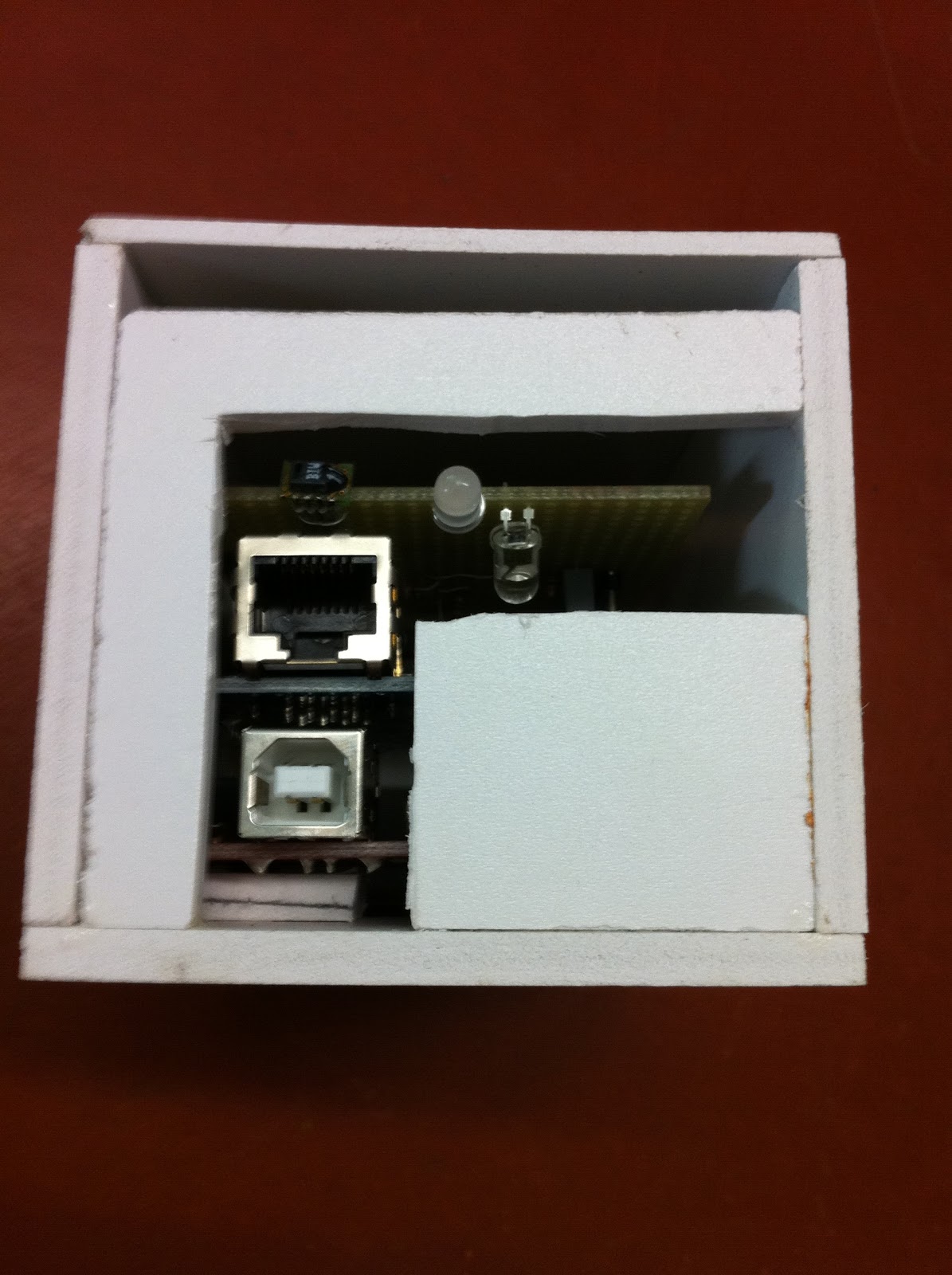
Engineer and build a small box, including an Arduino with ethernet shield, some visible leds, a local power supply, and sensor connections. Each rack will have its box, and these will be connected to an autonomous monitoring vlan.
A central Zabbix system will collect data from the boxes, manage historical series, and eventually generate alerts via email and sms (sms are sent via a bluetooth connection to a dedicated cellphone, so to be independent from main network availability)
Project state:
Underway, with prototype already working.
Description:
We are using Arduino 2009 boards, with ethernet shields.
Due to the arduino integration with ethernet shield, some pins are not available.
The available pins are:
Digital pins 2-9 (total 8 lines)
Analog pins 0-5 (total 6 lines)
Network Addressing:
Each box needs to have a unique mac address and ip address. To keep circuit simple and avoid dip switches, we decided to "burn" this configuration directly on the code. Each box gets a personalized code, which differs just for mac and ip address configuration. The code is uploaded to each box via usb interface, upon setup. The address is then written on a label on each box.
We discarded the option of implementing dhcp, because in any case we would have needed a software definition of a unique mac address.
Power:
Each unit is powered via a small and cheap USB power supply, to be connected to the local rack power. (here is a picture of the power supply)
Sensors:
We are planning to connect to each environmental monitoring box the following sensors:
Front Rack Door: open/close, with a simple switch, on a digital pin.
Back Rack Door: open/close, with a simple switch, on a digital pin.
Temperature & Humidity: Here I have some options, and I have to choose the best one.
- Temperature Option1: a simple thermistor, to be connected to an analog pin, in parallel with a resistor. This is very cheap, but requires calibration.
- Temperature Option2: a National LM35 sensor, to be connected to an analog pin. This is cheap, and should be linear, with 0,5 °C accuracy which is ok for me. This should be ok if I put the sensor in the box itself.
- Temperature Option3: a Dallas Semiconductor DS18S20 digital thermometer sensor, to be interfaced via 1-wire protocol a digital pin. This also has 0,5 °C accuracy, and should allow to use a longer cable and have the sensor at a longer distance from the box. I am afraid this is not going to be cheap.
- Temperature + Humidity Option 1: a Sensirion SHT1x. This is a digital sensor that reads both temperature and humidity. It is already calibrated. I am afraid this is not going to be cheap, but there are many variants of this sensor, from the low-end SHT10 to the high-end SHT75. I need to ask about prices.
- Temperature + Humidity Option 2: I found the Kele/Precon HS2000V which is an analog sensor that reads both temperature and humidity. This could be connected to two analog pins, and requires power. I could embed this sensor in the box itself.
The quite difficult part was to solder it, because the contacts are very small and close each other. Also the device is quite delicate, and soldering has to be done quickly not to damage it.
Smoke:
I built a simple sensor, made of two components: an infrared led, and an infrared photodiode. The infrared photodiode is mounted about 5cm apart from the led, and I put a heat shrinking tube on it. The resistor for the infrared led and for the photodiode are selected so to allow a "weak" reading which is altered by smoke on the ir path.
The photodiode output is sampled in an analog input. In this way, if some smoke gets in the middle, the output will change, and it can be detected.
Flood:
I have to find (or maybe build) the proper sensor.
Current Prototype:
Actual product, as delivered to the customers
The Arduino 2009 with atmega328, the wiznet ethernet shield, and a small hand made custom shield for our circuitry, have been packaged in hand made boxes.
I choose Simona.de Simona sheet 6mm and 3mm (a PVC foam material used in building and for making signs, also called FOREX or FOAMEX) as the material for the boxes. It is quite cheap.
It is easy to cut, easy to glue, and has enough rigidity to allow screws. This material is fire resistant, easy to work and well suited for its strenght.
As of november 2011, some dozens of these box have been built, and they work seamlessly in several datacenter environments.
Software:
I already hacked something which is working, at least to perform some tests with the zabbix central sampling engine. Each Arduino box runs a webserver, which is providing in its page the reading of all the sensors.
On the Zabbix server, there is a polling process and a parser which decodes the data, and archives it, eventually generating alarms.
I will update the code posted here as soon it is a bit more refined.
Here you have the code that runs on the arduino, to read the reed sensors (digital pin 4), and the temperature and humidity sensor (via digital pins 5 and 6). Reed sensors are to be put in series, so whatever is open triggers the door open alarm.
Analog pin 0 will be used for smoke sensor, but code is not yet here.
Digital pins 2 and 3 are used to briefly flash two colored leds, that in the future will become the box visual interface.
(CAVEATS: the following source code has been copied and pasted from the IDE to the blog, and this process unfortunately changed a bit some code lines, when they contain HTML tags. Beware!)
/* * Arduino + Ethernetshield (Wiznet) * datacenter sensor box * TOMBOX * Marco Guardigli mgua@tomware.it * this code is GPL, see www.gnu.org * see http://marco.guardigli.it/2010/05/arduino-in-datacenter-rack.html * * developed on arduino 21 ide, oct 2010. * * based on arduino Web Server example code * SHT-11 portions shamelessly adapted from the following sources * http://bbrack.net/Decimilia/sht1x.pde * and * http://www.railsimstuff.com/files/SHT11.pde * http://www.nuelectronics.com/download/projects/sht10_float.pde * * sensor reading happens when http request comes in. * sensors are not read if there are not incoming http requests * It works this way so to have a central monitoring software to * perform http reads * * in the future snmp trap to a remote server will probably be added * as well as polling independent sensor readings * * components: * reed magnetic sensor (on digital pin 4) * sensirion sht-11 temp+humidity sensor (digital pins 5,6) * home made smoke sensor, with infrared led and photodiode analog output (on analog pin 0) * free digital i/o: 7,8,9 * free analog i/o: 1,2,3,4,5 * * Pin Connections (SHT-11 pin count starts from top left going down: the right pins are not connected) * SHT-11 - arduino netshield * 1 gnd - gnd * 2 DATA - digital 6 * 3 SCK - digital 5 * 4 VDD - 5V * */ #include#include #define DATA 6 /* Arduino pin for SHT11 data read/write */ #define CLOCK 5 /* Arduino pin for toggling the clock */ #define NOACK 0 /* Flags to tell read_byte routine whether */ #define ACK 1 /* or not to send an ACK after the read */ /* Define the SHT1x commands to be their command codes */ #define MEASURE_TEMP 0x03 #define MEASURE_HUMI 0x05 #define STATUS_REG_W 0x06 #define STATUS_REG_R 0x07 #define RESET 0x1e /* Following constants are in microseconds */ #define LONG_DELAY delayMicroseconds(50) #define MEDIUM_DELAY delayMicroseconds(10) #define SHORT_DELAY delayMicroseconds(5) unsigned char debug; /* When set, intermediate data is printed */ #define ALERTLED 2 /* bicolor led, RED, on if LOW */ #define OKLED 3 /* bicolor led, RED, on if LOW */ #define OKBLINK 20000 /* loops for OK led blink */ #define ALERTBLINK 3000 /* loops for OK led blink */ int i; byte mac[] = { 0xDE, 0xAD, 0xBA, 0xEF, 0x00, 0x01 }; byte ip[] = { 172, 30, 4, 177 }; Server server(80); int okcnt = OKBLINK; int alertcnt = ALERTBLINK; int okledstate = LOW; /* led is on if state is LOW */ int alertledstate = HIGH; /* led is on if state is LOW */ int alert = false; /* this goes true if we are in alert state. When this is true, alert led blinks */ /** * sWriteByte * * Routine to write a byte to the SHT1x and check for the acknowledge * * Parameters: * @value byte value to be written * * Returns: * 0 for success, 1 if no Acknowledge received from SHT1x */ char sWriteByte(unsigned char value) { unsigned char ix; /* loop index */ unsigned char error; /* result of the write */ pinMode (DATA, OUTPUT); for (ix = 0x80; ix; ix >>= 1) { digitalWrite (DATA, ix & value);/* Next bit to I/O port */ SHORT_DELAY; /* Shouldn't be needed */ digitalWrite (CLOCK, HIGH); /* Set clock signal high */ MEDIUM_DELAY; /* some delay needed */ digitalWrite (CLOCK, LOW); /* Set clock back to low */ } pinMode (DATA, INPUT); /* Prepare to read the ACK bit */ digitalWrite (DATA, HIGH); /* Engage pull-up resistor */ digitalWrite (CLOCK, HIGH); /* Send 9th clock for ack) */ SHORT_DELAY; error = digitalRead (DATA); /* Expect pulled down by SHT1x */ digitalWrite (CLOCK, LOW); /* complete the clock pulse */ return error; } /** * sReadByte * * Routine to read one byte from the SHT1x. An acknowledge may or * may not be generated, according to the routine's argument. * * Parameters: * @sendAck If non-zero, an ACK is sent to the SHT1x if * the read was successful. * * Returns: * The value read from the SHT1x */ char sReadByte (unsigned char sendAck) { unsigned char ix; /* loop index */ unsigned char val = 0; /* for building the received data */ /* * Note to Bill: we should assure DATA is input by default * and get rid of these next two lines */ pinMode (DATA, INPUT); /* Set data pin for input mode */ digitalWrite (DATA, HIGH); /* Engage pull-up resistor */ for (ix = 0x80; ix; ix >>= 1) { digitalWrite (CLOCK, HIGH); /* High tells SHT1x we're reading */ SHORT_DELAY; if (digitalRead (DATA)) val |= ix; /* If DATA high, set corr. bit */ digitalWrite (CLOCK, LOW); /* Tell SHT1x ready for next bit */ SHORT_DELAY; } pinMode (DATA, OUTPUT); /* Change mode to prepare for ack */ digitalWrite (DATA, !sendAck); /* Set DATA LOW if sendAck requested */ SHORT_DELAY; digitalWrite (CLOCK, HIGH); /* Let SHT1x get the data */ MEDIUM_DELAY; /* delay for safety */ digitalWrite (CLOCK, LOW); /* Signal we're done with this */ pinMode (DATA, INPUT); /* Return Arduino pin to input */ digitalWrite (DATA, HIGH); /* And engage the pull-up */ return val; } /** * sTransmitStart * * Routine to generate a "Transmission Start", which looks like: * * _______ _______ * DATA: |_________| * ____ ____ * CLOCK: _____| |____| |____ * * Parameters: * None * * Returns: * No return value. */ void sTransmitStart (void) { pinMode (DATA, OUTPUT); /* Set DATA mode output */ digitalWrite (DATA, HIGH); /* Start DATA in high state */ digitalWrite (CLOCK, LOW); MEDIUM_DELAY; digitalWrite (CLOCK, HIGH); MEDIUM_DELAY; digitalWrite (DATA, LOW); MEDIUM_DELAY; digitalWrite (CLOCK, LOW); LONG_DELAY; digitalWrite (CLOCK, HIGH); MEDIUM_DELAY; digitalWrite (DATA, HIGH); MEDIUM_DELAY; digitalWrite (CLOCK, LOW); /* This routine will normally be followed by a write, so leave pinMode */ } /** * sConnectionReset * * Routine to generate a transmission reset, i.e. reset the SHT1x * to a known state to begin a transmission. It produces a pulse * train that looks like this: * _____________________________________________________ _____ * DATA: |_______| * _ _ _ _ _ _ _ _ _ ___ ___ * SCK : __| |__| |__| |__| |__| |__| |__| |__| |__| |______| |___| |___ * * Parameters: * None * * Returns: * No return value. */ void sConnectionReset (void) { unsigned char ix; pinMode (DATA, OUTPUT); /* Set Data to output mode */ digitalWrite (DATA, HIGH); /* Start Data in high state */ digitalWrite (CLOCK, LOW); /* Start Clock in low state */ /* Now generate 9 clock "pulses" */ for (ix = 0; ix < 9; ix++) { SHORT_DELAY; digitalWrite (CLOCK, HIGH); SHORT_DELAY; digitalWrite (CLOCK, LOW); } sTransmitStart (); /* Follow with start pulse */ } /** * sSoftReset * * Routine to do a "soft" reset, i.e. send a "Reset" command to the SHT1x * * Parameters: * None * * Returns: * 0 for success, 1 if bad response from SHT1x */ char sSoftReset (void) { sConnectionReset (); /* Reset SHT1x communication */ return sWriteByte (RESET); /* Send command and return result */ } /** * doCRC * * Routine to calculate the CRC while message is sent / received * * Parameters: * @ch character to be added to CRC * @crc crc to which character is to be added * * Returns: * Target CRC value is updated */ #define CRC_POLY 0x31 /* CRC polynomial x**8 + x**5 + x**4 */ void doCRC (unsigned char ch, unsigned char *crc) { int ix; unsigned char b7; for (ix = 0; ix < 8; ix++) { b7 = ch ^ *crc; *crc <<= 1; ch <<= 1; if (b7 & 0x80) *crc ^= CRC_POLY; } return; } /** * sMeasure * * Routine to make a measurement of either temperature or humidity, and * return the result. * * Parameters: * @pValue pointer to where value should be stored * @command command to be sent to the SHT1x * @singleFlag Flag to show a single byte only should be read * * Returns: * Returns the status from the 'read' of the data, and places the value * read into the the locations pointed at by the arguments. Note that the * SHT1x returns data as (MSB, LSB) so this routine stores the * (short integer) value in reverse sequence. */ char sMeasure (unsigned char *pValue, unsigned char command, unsigned char singleFlag) { unsigned char error; /* holds return value from routine */ unsigned int ix; /* used for 'wait for data' loop */ unsigned char ch, crc, revCRC; crc = 0; /* Initialize CRC to zero */ sTransmitStart (); /* Start transmission of command */ error = sWriteByte (command); /* Send the requested command */ /* Note that sWriteByte leaves DATA in input mode */ doCRC (command, &crc); /* Include command in CRC */ if (debug) { Serial.print("After 'command': CRC is 0x"); Serial.println(crc, HEX); } for (ix = 0; ix < 65535; ix++) if (!digitalRead (DATA)) break; if (digitalRead (DATA)) Serial.println("DATA did not go low after writing command"); if (!singleFlag) { /* If a 2-byte reply */ ch = sReadByte (ACK); /* Read MSB of data */ doCRC (ch, &crc); /* Include in CRC */ if (debug) { Serial.print("After MSB: CRC is 0x"); Serial.println(crc, HEX); } *(pValue + 1) = ch; /* Store MSB byte */ } ch = sReadByte (ACK); /* Read LSB of data */ doCRC (ch, &crc); /* Include in CRC */ *pValue = ch; /* Store LSB byte */ if (debug) { Serial.print("After LSB: CRC is 0x"); Serial.println(crc, HEX); } ch = sReadByte (NOACK); /* Read msg CRC, don't send ACK */ revCRC = 0; for (ix = 0; ix < 8; ix++) { if ((0x80 >> ix) & ch) revCRC |= (1 << ix); } if (debug) { Serial.print("After Checksum: CRC is 0x"); Serial.print(crc, HEX); Serial.print(", received value was 0x"); Serial.println(revCRC, HEX); } if (crc != revCRC) { Serial.print("CRC error in reply (command was 0x"); Serial.print(command, HEX); Serial.print("CRC is 0x"); Serial.print(crc, HEX); Serial.print(", received value was 0x"); Serial.println(revCRC, HEX); Serial.println(") - resetting SHT1x connection"); sConnectionReset(); } return error; } /** * calcTempHumid * * Routine to calculate the "true" temperature and humidity based upon * the "tick" values read from the SHT1x. The SHT1x is set to operate in * 12-bit mode for humidity, and 14-bit mode for temperature. The * conversion constants are taken from the SHT1x datasheet, assuming a * supply voltage of 5.0V. * * Parameters: * @pHumidity pointer to humidity value * @pTemperature pointer to temperature value * * Returns: * Input values of temperature and humidity are overwritten with their * calculated "true" values. */ void calcTempHumid (float *pHumidity, float *pTemperature) { /* Constants for conversion of reading to relative humidity */ #define C1 -4.0 #define C2 +0.0405 #define C3 -0.0000028 /* Constants for temperature-compensated relative humidity */ #define T1 +0.01 #define T2 +0.00008 /* Constants for conversion of temperature reading to Centigrade */ #define D1 -40.00 #define D2 +0.01 float rh = *pHumidity; /* relative humidity (input value) */ float rhLin; /* Linear value of humidity */ float rhTrue; /* Temperature-compensated humidity value */ float t = *pTemperature; /* input value for temperature */ float tC; /* Temperature converted to Celsius */ tC = D1 + (t * D2); /* Linear conversion of temperature */ rhLin = (C3 * rh * rh) + (C2 * rh) + C1; /* "ticks" to relative H */ rhTrue = (tC - 25) * (T1 + (T2 * rh)) + rhLin; /* Assure our relative humidity isn't out of range (> 100% or < 0.1%) */ if (rhTrue > 100.0) rhTrue = 100.0; else if (rhTrue < 0.1) rhTrue = 0.1; /* Finally, return the calculated values */ *pTemperature = tC; *pHumidity = rhTrue; } /** * calcDewPoint * * Routine to calculate the dew point based upon relative humidity * and temperature. I have no idea what it's doing, but since it * comes from the Sensirion literature, it's probably correct :-). * * Parameters: * @humidity value of relative humidity * @temperature value of temperature * * Returns: * Calculated dew point */ float calcDewPoint (float humidity, float temperature) { float logEx; logEx = 0.66077 + (7.5 * temperature) / (237.3 + temperature) + (log10(humidity) - 2); return (logEx - 0.66077) * 237.3 / (0.66077 + 7.5 - logEx); } /** * splitFloat * * This routine takes a float as input and returns the integer part and * the fractional part, to the number of decimal places specified. The * only reason I wrote it is because I couldn't find any existing routine * to print out a float in a reasonable format (with decimal places) * * Parameters: * @fNum The floating point number to be dissected * @pInt Pointer to an integer to contain the integer part * @pFrac Pointer to a string to contain the fraction * Note: the caller must assure the string is large enough * @decPlaces Number of decimal places for the operation * * Returns: * The values calculated are placed in the locations specified. */ void splitFloat (float *fNum, int *pInt, char *pFrac, int decPlaces) { int ix; int frac; float fVal; /* Round the input according to precision, plus fudge for noise */ fVal = *fNum + (0.5 * pow(10.0, (float)(-decPlaces))) + 0.00001; *pInt = fVal; /* Return truncated integer value */ /* * Now isolate just the fractional part of the original number */ fVal = fVal - (float)(*pInt); /* Remove the integral part */ /* Convert the fraction into a simple integer */ frac = fVal * pow (10.0, (float)decPlaces); /* Now format it as a leading-zero string of digits */ pFrac += decPlaces; /* point to string terminator position */ *pFrac-- = 0; /* put in terminator */ for (ix = 0; ix < decPlaces; ix++) { *pFrac-- = (frac % 10) | 0x30; /* put in digits in reverse order */ frac /= 10; } } /** * printReading * * Routine to print out the value of caculated data, using a common format * of {label} {int value}.{single digit fraction}{suffix} * * Parameters: * @label string for starting label * @pVal pointer to float value to display * @suffix string to append to value * * Returns: * nothing */ void printReading (char *label, float *pVal, char *suffix) { int num; char str[10]; splitFloat (pVal, &num, str, 1); Serial.print(label); Serial.print(num, DEC); Serial.print("."); Serial.print(str); Serial.println(suffix); } void loop2() { char cmd; /* command input by user */ int humidVal; /* humidity value read from SHT1x */ int tempVal; /* temperature value from SHT1x */ unsigned char statusVal; /* contents of status register */ float fHumidity; /* working value for humidity calculation */ float fTemperature; /* working value for temperature calculation */ float dewPoint; /* calculated Dew Point value */ unsigned char error; /* return value for routine calls */ while (Serial.available() > 0) { /* when a serial connection exists */ cmd = Serial.read(); /* Read user comand */ error = 0; switch (cmd) { case 'r': case 'R': /* Read request - read in temperature and humidity */ error += sMeasure ((unsigned char *)&humidVal, MEASURE_HUMI, 0); if (debug) { Serial.print("In main loop: humidVal is "); Serial.print(humidVal, HEX); Serial.print(" and return value is "); Serial.println(error, DEC); } error += sMeasure ((unsigned char *)&tempVal, MEASURE_TEMP, 0); if (debug) { Serial.print("In main loop: tempVal is "); Serial.print(tempVal, HEX); Serial.print(" and return value is "); Serial.println(error, DEC); } if (error) sConnectionReset(); else { fHumidity = float(humidVal); fTemperature = float(tempVal); calcTempHumid (&fHumidity, &fTemperature); dewPoint = calcDewPoint (fHumidity, fTemperature); printReading ("Temperature is ", &fTemperature, "\xb0 Celsius"); printReading ("Humidity is ", &fHumidity, "%"); printReading ("Dew point is ", &dewPoint, "\xb0 Celsius"); } break; case 'd': /* "Toggle" debug flag for printing */ case 'D': /* intermediate data */ debug ^= 1; if (debug) Serial.println("**** Debugging enabled ****"); else Serial.println("**** Debugging disabled ****"); break; case 's': /* Read status register */ case 'S': /* Read request - read in temperature and humidity */ error += sMeasure ((unsigned char *)&statusVal, STATUS_REG_R, 1); Serial.print("Status register contains 0x"); Serial.println(statusVal, HEX); break; default: Serial.println("Unrecognized command."); } } } void toggleAlertLed(){ if (alert && alertledstate == HIGH) alertledstate = LOW; else alertledstate = HIGH; } void toggleOkLed(){ if (okledstate == HIGH) okledstate = LOW; else okledstate = HIGH; } void greeting(){ /* interface led greeting */ pinMode(OKLED, OUTPUT); digitalWrite(OKLED,LOW); delay(250); /* green show */ digitalWrite(OKLED,HIGH); delay(500); pinMode(ALERTLED, OUTPUT); digitalWrite(ALERTLED,LOW); delay(250); /* red show */ digitalWrite(ALERTLED,HIGH); delay(500); digitalWrite(OKLED,LOW); digitalWrite(ALERTLED,LOW); delay(500); /* amber show */ digitalWrite(ALERTLED,HIGH); /* set green */ } void setup() { okcnt = OKBLINK; alertcnt = ALERTBLINK; okledstate = LOW; /* led is on when state is LOW */ alertledstate = HIGH; /* led is off when state is high */ Serial.begin(9600); /* Open Arduino serial communications */ Serial.println("Setup."); pinMode (CLOCK, OUTPUT); /* set pins for SHT-11 */ pinMode (DATA, OUTPUT); /* set pins for SHT-11 */ sConnectionReset (); /* Reset the SHT11 device */ Ethernet.begin(mac, ip); server.begin(); greeting(); /* flash led interface */ } void loop() { char cmd; /* command input by user */ int humidVal; /* humidity value read from SHT1x */ int tempVal; /* temperature value from SHT1x */ unsigned char statusVal; /* contents of status register */ float fHumidity; /* working value for humidity calculation */ float fTemperature; /* working value for temperature calculation */ float dewPoint; /* calculated Dew Point value */ unsigned char error; /* return value for routine calls */ int num; char str[10]; Client client = server.available(); if (client) { // an http request ends with a blank line boolean current_line_is_blank = true; while (client.connected()) { if (client.available()) { char c = client.read(); // if we've gotten to the end of the line (received a newline // character) and the line is blank, the http request has ended, // so we can send a reply if (c == '\n' && current_line_is_blank) { // send a standard http response header client.println("HTTP/1.1 200 OK"); client.println("Content-Type: text/html"); client.println(); Serial.println("Serving page."); client.println(" TomWare tombox v1 (oct 2010)
"); client.println("Arduino sensing and monitoring box "); client.println("mgua@tomware.it "); client.println("digital pin 2,3: bicolor Led red/green cathodes "); client.println("digital pin 4: reed magnetic sensor "); client.println("digital pins 5,6: clk,data of SHT-11 temp and humidity sensor "); client.println("Analog pin 0: smoke sensor "); client.println("
"); client.println("The 0-5 (6) analog (0-1023) lines "); for (i = 0; i < 6; i++) { client.print("analog input "); client.print(i); client.print(" is "); client.print(analogRead(i)); client.println(" "); } client.println("
"); client.println("The 2-4 digital (0-1) lines "); for (i = 2; i < 5; i++) { client.print("digital input "); client.print(i); client.print(" is "); client.print(digitalRead(i)); client.println(" "); } client.println("The 7-9 digital (0-1) lines "); for (i = 7; i < 10; i++) { client.print("digital input "); client.print(i); client.print(" is "); client.print(digitalRead(i)); client.println(" "); } client.println("
"); // ---------Temp & Humid readings ------------------------------ error = 0; error += sMeasure ((unsigned char *)&humidVal, MEASURE_HUMI, 0); error += sMeasure ((unsigned char *)&tempVal, MEASURE_TEMP, 0); if (error) { client.println(" SHT11 error, resetting... "); sConnectionReset(); } else { fHumidity = float(humidVal); fTemperature = float(tempVal); calcTempHumid (&fHumidity, &fTemperature); dewPoint = calcDewPoint (fHumidity, fTemperature); client.print("Temperature: "); splitFloat (&fTemperature, &num, str, 1); client.print(num, DEC); client.print("."); client.print(str); client.println("\xb0 Celsius"); client.println(" "); /* temperature alert threshold */ if (num > 30) { Serial.println("temp threshold exceeded."); alert = true; } else { alert = false; } /* --------------------------- */ client.print("Humidity: "); splitFloat (&fHumidity, &num, str, 1); client.print(num, DEC); client.print("."); client.print(str); client.println("%"); client.println(" "); client.print("Dew point: "); splitFloat (&dewPoint, &num, str, 1); client.print(num, DEC); client.print("."); client.print(str); client.println("\xb0 Celsius"); client.println(" "); } /* Notify on green led that page serving is in progress inverting its state */ toggleOkLed(); pinMode(OKLED, OUTPUT); digitalWrite(OKLED,okledstate); /* client.println("
The 2-4 (3) briefly output digital (0-1) lines "); for (int i = 2; i < 5; i++) { pinMode(i, OUTPUT); digitalWrite(i,LOW); delay(10); pinMode(i, INPUT); delay(10); } */ break; } if (c == '\n') { // we're starting a new line current_line_is_blank = true; } else if (c != '\r') { // we've gotten a character on the current line current_line_is_blank = false; } } } // give the web browser time to receive the data delay(1); client.stop(); } // --------- Led Blinking ------------------------------ okcnt--; if (okcnt < 1) { okcnt = OKBLINK; toggleOkLed(); pinMode(OKLED, OUTPUT); digitalWrite(OKLED,okledstate); } alertcnt--; if (alertcnt < 1) { alertcnt = ALERTBLINK; toggleAlertLed(); pinMode(ALERTLED, OUTPUT); digitalWrite(ALERTLED,alertledstate); } // --------- Led Blinking end ------------------------------ }
Marco ( @mgua on twitter)
.
Thursday, May 20, 2010
online countries
If social networks or online communities are going to become political entities, someone will say:
Where are you from?
I am from Facebook, and you?
I am from Twitter.
Online countries establish laws and taxes.
---
A facebooker, an ebayer and a twitterzen once met in second life:
I sell my privacy everyday: said the facebooker.
I sell my things everyday: said the ebayer.
I sell my opinions everyday, said the twitterzen.
Is sharing a lot different than selling?
Does the price really matter, if it is not paid in money?
---
See also this previous post of mine: evaporating borders.
m
( @mgua on twitter )
Where are you from?
I am from Facebook, and you?
I am from Twitter.
Online countries establish laws and taxes.
---
A facebooker, an ebayer and a twitterzen once met in second life:
I sell my privacy everyday: said the facebooker.
I sell my things everyday: said the ebayer.
I sell my opinions everyday, said the twitterzen.
Is sharing a lot different than selling?
Does the price really matter, if it is not paid in money?
---
See also this previous post of mine: evaporating borders.
m
( @mgua on twitter )
Wednesday, May 12, 2010
3D printing everywhere: commoditization of reality
Tridimensional TV is about to arrive, soon after the big boom of 3D movies currently exploding.
Tridimensional printing will be the next wave.
Technologies for tridimensional printing are not new, but recently they are getting a huge push and we will soon have low cost tridimensional printing at a very low cost.
This will probably completely change the world of manufacturing and have huge impact on logistics too.
Commoditization of reality means that manufacturing and distribution costs for whatever object will drop while availability will go up. This will be quite a revolutionary change in traditional manufacturing processes.
Tridimensional printing will evolve from easy to sell solutions for building simple things, in plastic and resins, to multi-material and high resolution and high precision objects.
Nanoscale three dimensional printing will ultimately allow to build whatever object in molecular resolution.
Some scientific data:
We currently have atomic scale accurate positioning in multilayer microelecronics, currently used in building memories and processors, with metals and semiconductors. These technologies are based on masking techniques, and thin layer (a few molecules) depositing of various materials.
We are developing increasing accurate technologies for 3-dimensional scanning, and currently the resolution of living tissue MRI imaging is ranging in the 20micrometers (20 * 10 ^-6 m) and we have MRFM (Magnetic Resonance Force Microscopy) able to "see" at resolution of some nanometers (5 * 10^-9 m).
There are significant studies available, like Minimal Manufacturing, by Kazuhiro Murata (AIST, Japan) where "ink" jet printing technology is considered as the future of manufacturing.
Current superfine ink jet printing can individually address and place sub micrometer sized dots (0.5 * 10^-6 m)
In the future, the difficulty will be not to build, because ink manufacturing will ease and allow much cheaper object building.
Advances in 3-d printing will allow cheap manufacturing, and very easy transition from design to objects.
------
Some pointers:
Do It yourself 3d printing:
Here is the reprap project, conceived to be completely open and self reproducing
And here is the makerbot project, similar, but less focused on self reproduction.
check also this for large scale object printing
3D printing is also for medical usage. Check organ printing and this.
Marco
( @mgua on twitter )
.
Tridimensional printing will be the next wave.
Technologies for tridimensional printing are not new, but recently they are getting a huge push and we will soon have low cost tridimensional printing at a very low cost.
This will probably completely change the world of manufacturing and have huge impact on logistics too.
Commoditization of reality means that manufacturing and distribution costs for whatever object will drop while availability will go up. This will be quite a revolutionary change in traditional manufacturing processes.
Tridimensional printing will evolve from easy to sell solutions for building simple things, in plastic and resins, to multi-material and high resolution and high precision objects.
Nanoscale three dimensional printing will ultimately allow to build whatever object in molecular resolution.
Some scientific data:
We currently have atomic scale accurate positioning in multilayer microelecronics, currently used in building memories and processors, with metals and semiconductors. These technologies are based on masking techniques, and thin layer (a few molecules) depositing of various materials.
We are developing increasing accurate technologies for 3-dimensional scanning, and currently the resolution of living tissue MRI imaging is ranging in the 20micrometers (20 * 10 ^-6 m) and we have MRFM (Magnetic Resonance Force Microscopy) able to "see" at resolution of some nanometers (5 * 10^-9 m).
There are significant studies available, like Minimal Manufacturing, by Kazuhiro Murata (AIST, Japan) where "ink" jet printing technology is considered as the future of manufacturing.
Current superfine ink jet printing can individually address and place sub micrometer sized dots (0.5 * 10^-6 m)
In the future, the difficulty will be not to build, because ink manufacturing will ease and allow much cheaper object building.
Advances in 3-d printing will allow cheap manufacturing, and very easy transition from design to objects.
------
Some pointers:
Do It yourself 3d printing:
Here is the reprap project, conceived to be completely open and self reproducing
RepRap from Adrian Bowyer on Vimeo.
And here is the makerbot project, similar, but less focused on self reproduction.
check also this for large scale object printing
3D printing is also for medical usage. Check organ printing and this.
Marco
( @mgua on twitter )
.
Sunday, March 28, 2010
Improving the world in small steps
World improvement projects do not necessarily need to be huge.
I believe in bottom-up approaches
Evolution is a bottom-up world improvement undirectedproject agent.
How to make a better world
We improve the world
every time we teach
every time we learn
whenever we avoid an unnecessary waste
whenever we share a good idea
with every smile
with every good action
We improve the world
in helping each other
in showing positive attitude
in spreading culture
in promoting critical thinking
and avoiding prejudices
in not accepting a ready-made reality
or a pre-digested truth
in showing how things really are
despite the propaganda.
We improve the world
when we put aside our racisms
when we value our differences
when we consider many options
when we put in each other shoes,
when we allow choices
when we accept and consider
different point of views
at the same time
We improve the world
building things
dreaming and inventing,
thinking,
sharing,
and constantly looking for better ways.
Marco ( @mgua on twitter )
.
I believe in bottom-up approaches
Evolution is a bottom-up world improvement undirected
How to make a better world
We improve the world
every time we teach
every time we learn
whenever we avoid an unnecessary waste
whenever we share a good idea
with every smile
with every good action
We improve the world
in helping each other
in showing positive attitude
in spreading culture
in promoting critical thinking
and avoiding prejudices
in not accepting a ready-made reality
or a pre-digested truth
in showing how things really are
despite the propaganda.
We improve the world
when we put aside our racisms
when we value our differences
when we consider many options
when we put in each other shoes,
when we allow choices
when we accept and consider
different point of views
at the same time
We improve the world
building things
dreaming and inventing,
thinking,
sharing,
and constantly looking for better ways.
Marco ( @mgua on twitter )
.
Monday, March 22, 2010
Spring, finally
Today it is the first day of Spring.
We had a decent weekend after a quite bad winter season.
Even one of our turtles woke up after the winter letargy.
...And I still have to prune trees and trim hedges in my garden. I am lazy.
Today I had the chance of flying one of my rc planes for the first time after the winter.
And it was great. My kids enjoyed it. Lots of other kids were watching. I also had a somewhat hard landing against a tree and so I had to use some glue to fix a small break.
We did not have a super bright sunny day, but it was enough.
I hope that next weekend will be better.
Marco
We had a decent weekend after a quite bad winter season.
Even one of our turtles woke up after the winter letargy.
...And I still have to prune trees and trim hedges in my garden. I am lazy.
Today I had the chance of flying one of my rc planes for the first time after the winter.
And it was great. My kids enjoyed it. Lots of other kids were watching. I also had a somewhat hard landing against a tree and so I had to use some glue to fix a small break.
We did not have a super bright sunny day, but it was enough.
I hope that next weekend will be better.
Marco
Sunday, February 21, 2010
Will life extension cause tyrants oligarchies?
Life extension technologies are almost here.
Soon it will be possible to cure bodies from aging.
These cures will be probably very expensive, and initially access will be limited to the extremely rich.
What will this bring?
Here are a couple of possible futures:
Very Scary scenario:
Life extension treatments will be accessible only to a very small elite, made of ultra-rich, political and biotech leaders.
They will actually perpetuate the chain of power in their own hands, tightly controlling drugs and treatment access.
Masses will not have access to life extension, because of cost and sociopolitical control issues.
In this scenario, obviously the leaders will oppose to whatever change, as normally happens in dictatorship. This status will last indefinitely, because dictators will extend their lifespan.
Scary scenario:
Life extension treatments will be outrageously expensive in the beginning, then gradually the price will go down, becoming accessible to high class and middle-class citizens of developed countries. Since people will not die, population will be controlled by blocking, sanctioning or prohibiting reproduction.
New births will virtually cease. Children will not exist any more. Work will become eternal routine. Most people will become bored. Someone will decide to die/suicide, stopping taking the medecines.
Middle-age will become a sort of dull eternity. A gray limbo in which to stay, er... forever.
Psychotherapies will extend for centuries.
Time will lose or change its current meaning.
Interstellar trips will become feasible.
Digital transitionism will develop. People will be ablt to decide to go digital, evaporating into bits, leaving physical body and jumping into some digital virtual world.
Is anyone willing to share some other ideas for a hopefully happier future?
Marco ( @mgua on twitter )
.
Soon it will be possible to cure bodies from aging.
These cures will be probably very expensive, and initially access will be limited to the extremely rich.
What will this bring?
Here are a couple of possible futures:
Very Scary scenario:
Life extension treatments will be accessible only to a very small elite, made of ultra-rich, political and biotech leaders.
They will actually perpetuate the chain of power in their own hands, tightly controlling drugs and treatment access.
Masses will not have access to life extension, because of cost and sociopolitical control issues.
In this scenario, obviously the leaders will oppose to whatever change, as normally happens in dictatorship. This status will last indefinitely, because dictators will extend their lifespan.
Scary scenario:
Life extension treatments will be outrageously expensive in the beginning, then gradually the price will go down, becoming accessible to high class and middle-class citizens of developed countries. Since people will not die, population will be controlled by blocking, sanctioning or prohibiting reproduction.
New births will virtually cease. Children will not exist any more. Work will become eternal routine. Most people will become bored. Someone will decide to die/suicide, stopping taking the medecines.
Middle-age will become a sort of dull eternity. A gray limbo in which to stay, er... forever.
Psychotherapies will extend for centuries.
Time will lose or change its current meaning.
Interstellar trips will become feasible.
Digital transitionism will develop. People will be ablt to decide to go digital, evaporating into bits, leaving physical body and jumping into some digital virtual world.
Is anyone willing to share some other ideas for a hopefully happier future?
Marco ( @mgua on twitter )
.
Saturday, February 6, 2010
screen view change basing on user face position
Here is another project from my free-time personal exploration of CV (Computer Vision).
The idea is to enhance human to computer interface via the detection of user face position in front of the screen.
The screen image is updated in real-time taking into account the head position of the user.
This is one of the many possible ways of building a 3D vision, but this method works only for one user at a time.
This project is developed in Processing, and requires the OpenCV library. I used the same setup described in the Arduino Processing Face Follower and in the previous Two Axis Controlled Laser Gun
The main idea is to adapt the presentation of a 3D image shown in a window, taking into account the user face coordinates, as detected from the webcam incoming flow.
Here is a (er.. ugly) video
I am sorry but the quality is quite low. My phone camera is not that good.
Description
A tridimensional object is shown on the screen, and it is rendered taking into account the viewing position of the user, determined by the position of his face, as detected by the webcam.
The code is not particularly clean and should be improved, but works.A future version will reduce some flickering due to mistakes in continuosly detecting the user face position, expecially near the boundaries of the webcam viewing field. (this was implemented in v. 0.3)
Code is reasonably parametric, basing on the initial windows resolution specifications maxx and maxy. If you change these values, or if you have a different webcam, some tweaking might be needed in the map statement used to define the value of r. (version 0.3)
Requirements
to have face detection algorithm working.
Please follow description of the setup in my other previously mentioned projects.
Code
Here is the Processing Code.
here is the 0.1 version (jan 31 2010)
here is the 0.2 version, with autorotation features.
here is the 0.3 version, with distance sensing and size dependent from distance (feb 6 2010)
here is the 0.4 version, with side colored lights and 3D boxes scattered around.
code listing of v 0.2 version is here:
/*
Processing and OpenCV code
Detects viewer face movement and redraws scene basing on face position
by Marco Guardigli, mgua@tomware.it @mgua on twitter
see http://marco.guardigli.it/2010/01/screen-view-change-basing-on-user-face.html
This code is released under GNU GPL license. See http://www.gnu.org
jan 31.2010 v 0.1 Marco Guardigli
v 0.2 Marco Guardigli, added autorotate
disabled distance sensing (not working well)
and introduced distance link to mouseX
*/
import hypermedia.video.*;
OpenCV opencv;
boolean DEBUG = true; // set to TRUE for some debug output
boolean AUTOROTATE = true; // set to true to enable autorotate
int maxx = 800; // window size x
int maxy = 600; // window size y
int cfacex, cfacey; // center of the first face detected
float fw, fh; // face width and face height (in relation to window size)
float rmin, rmax; // range of perceived distance
float fwmin, fwmax; // possible range of face width (auto defined)
float ex, ey, ez; // coordinates of the camera position (eye)
float upx, upy, upz; // rotation of the camera (default 0,1,0);
float cx, cy, cz; // center of the scene (where the camera points)
float ra; // distance of the camera from center of the scene
float r, r_p, r_pp; // 3 last values of measured distance, for averaging and smoothing
float drrp, maxdr;
float thxz, thxy, thyz; // angles on the three planes xz, xy, yz, growing counterclockwise 0-359
float fthxz, fthxy, fthyz; // angles on the three planes xz, xy, yz, for face
float athxz, athxy, athyz; // angles on the three planes xz, xy, yz, for autorotate
float dthxy; // quantum of autorotate angle change (degrees)
float dthxz; // quantum of autorotate angle change (degrees)
float radbydeg = TWO_PI / 360; // radians per degree
void setup() {
size(maxx, maxy, P3D);
fill(204);
r = 100;
cx = 0; cy = 0; cz = 0;
ex = r; ey = 0; ez = 0;
upx = 0; upy = 1; upz = 0;
thxz = 0; thxy = 0; thyz = 0;
rmax = 0; rmin = r; // initial values for minmax detection (switched on purpose)
ra = r; r_p = r; r_pp = r; // previous values for averaging
fwmin = 1; fwmax = 0; // initial values for minmax detection (switched on purpose)
opencv = new OpenCV(this);
opencv.capture( maxx, maxy );
opencv.cascade( OpenCV.CASCADE_FRONTALFACE_ALT ); // load the FRONTALFACE description file
opencv.read();
if (AUTOROTATE) {
dthxy = 0;
dthxz = 5; // vertical axis
}
}
void draw() {
lights();
background(0);
camera(ex, ey, ez, cx, cy, cz, upx, upy, upz);
stroke(255,255,0);
box(50,30,60); // draw a 3d solid composed of
box(40,20,70); // three simple intersecating
box(60,10,10); // boxes
opencv.read();
Rectangle[] faces = opencv.detect(); // detect anything resembling a FRONTALFACE
if (faces.length > 0) {
cfacex = faces[0].x; cfacey = faces[0].y;
fw = faces[0].width;
cfacex = cfacex + int(fw / 2); // cfacex = x center of face
fh = faces[0].height;
cfacey = cfacey + int(fh / 2); // cfacey = y center of face
fh = fh / maxy;
fw = fw / maxx; // portion of screen width taken by face width
if (fw < fwmin) { fwmin = fw; } // detect min and max face width for autoscale
if (fw > fwmax) { fwmax = fw; }
fthxy = map (cfacey,0,height,-40,40); // input range for xy is 80 degrees (-40..40)
fthxz = map (cfacex,0,width,-50,50); // input range for xz is 100 degrees (-50..50)
athxy = (athxy + dthxy) % 360; // dthxy and dthxz are autorotate steps
athxz = (athxz + dthxz) % 360;
thxy = (fthxy + athxy) % 360; // add autorotate to face position
thxz = (fthxz + athxz) % 360;
ex = ra * cos(thxz * radbydeg); // new camera coordinates x
ey = ra * sin(thxy * radbydeg); // new camera coordinates y
ez = ra * sin(thxz * radbydeg); // new camera coordinates z
ra = mouseX + 100;
if ( DEBUG ) {
println("cfacex,cfacey=[" + cfacex + "],[" + cfacey + "]");
println("facewidth,faceheight=[" + fw + "],[" + fh +"]");
println("fwmin,fwmax=[" + fwmin + "],[" + fwmax +"]");
println("r, rmin, rmax=[" + r + "],[" + rmin + "],[" + rmax + "]");
}
} else { println("face not detected"); }
}
Similar projects
TrackEye, Real-Time Tracking Of Human Eyes Using a Webcam: by Zafer Savas, is aimed at detecting user eyes coordinates.
Head Tracking for Desktop VR Displays using the Wii Remote: by Johnny Chung Lee, is a very nice hack that uses a wii remote device to sense the user head position thru the wii infrared sensor
Marco ( @mgua on twitter )
.
The idea is to enhance human to computer interface via the detection of user face position in front of the screen.
The screen image is updated in real-time taking into account the head position of the user.
This is one of the many possible ways of building a 3D vision, but this method works only for one user at a time.
This project is developed in Processing, and requires the OpenCV library. I used the same setup described in the Arduino Processing Face Follower and in the previous Two Axis Controlled Laser Gun
The main idea is to adapt the presentation of a 3D image shown in a window, taking into account the user face coordinates, as detected from the webcam incoming flow.
Here is a (er.. ugly) video
I am sorry but the quality is quite low. My phone camera is not that good.
Description
A tridimensional object is shown on the screen, and it is rendered taking into account the viewing position of the user, determined by the position of his face, as detected by the webcam.
The code is not particularly clean and should be improved, but works.
Code is reasonably parametric, basing on the initial windows resolution specifications maxx and maxy. If you change these values, or if you have a different webcam, some tweaking might be needed in the map statement used to define the value of r. (version 0.3)
Requirements
- A working Processing and OpenCV installation ( I did it on a Windows XP SP3)
- A webcam.
to have face detection algorithm working.
Please follow description of the setup in my other previously mentioned projects.
Code
Here is the Processing Code.
here is the 0.1 version (jan 31 2010)
here is the 0.2 version, with autorotation features.
here is the 0.3 version, with distance sensing and size dependent from distance (feb 6 2010)
here is the 0.4 version, with side colored lights and 3D boxes scattered around.
code listing of v 0.2 version is here:
/*
Processing and OpenCV code
Detects viewer face movement and redraws scene basing on face position
by Marco Guardigli, mgua@tomware.it @mgua on twitter
see http://marco.guardigli.it/2010/01/screen-view-change-basing-on-user-face.html
This code is released under GNU GPL license. See http://www.gnu.org
jan 31.2010 v 0.1 Marco Guardigli
v 0.2 Marco Guardigli, added autorotate
disabled distance sensing (not working well)
and introduced distance link to mouseX
*/
import hypermedia.video.*;
OpenCV opencv;
boolean DEBUG = true; // set to TRUE for some debug output
boolean AUTOROTATE = true; // set to true to enable autorotate
int maxx = 800; // window size x
int maxy = 600; // window size y
int cfacex, cfacey; // center of the first face detected
float fw, fh; // face width and face height (in relation to window size)
float rmin, rmax; // range of perceived distance
float fwmin, fwmax; // possible range of face width (auto defined)
float ex, ey, ez; // coordinates of the camera position (eye)
float upx, upy, upz; // rotation of the camera (default 0,1,0);
float cx, cy, cz; // center of the scene (where the camera points)
float ra; // distance of the camera from center of the scene
float r, r_p, r_pp; // 3 last values of measured distance, for averaging and smoothing
float drrp, maxdr;
float thxz, thxy, thyz; // angles on the three planes xz, xy, yz, growing counterclockwise 0-359
float fthxz, fthxy, fthyz; // angles on the three planes xz, xy, yz, for face
float athxz, athxy, athyz; // angles on the three planes xz, xy, yz, for autorotate
float dthxy; // quantum of autorotate angle change (degrees)
float dthxz; // quantum of autorotate angle change (degrees)
float radbydeg = TWO_PI / 360; // radians per degree
void setup() {
size(maxx, maxy, P3D);
fill(204);
r = 100;
cx = 0; cy = 0; cz = 0;
ex = r; ey = 0; ez = 0;
upx = 0; upy = 1; upz = 0;
thxz = 0; thxy = 0; thyz = 0;
rmax = 0; rmin = r; // initial values for minmax detection (switched on purpose)
ra = r; r_p = r; r_pp = r; // previous values for averaging
fwmin = 1; fwmax = 0; // initial values for minmax detection (switched on purpose)
opencv = new OpenCV(this);
opencv.capture( maxx, maxy );
opencv.cascade( OpenCV.CASCADE_FRONTALFACE_ALT ); // load the FRONTALFACE description file
opencv.read();
if (AUTOROTATE) {
dthxy = 0;
dthxz = 5; // vertical axis
}
}
void draw() {
lights();
background(0);
camera(ex, ey, ez, cx, cy, cz, upx, upy, upz);
stroke(255,255,0);
box(50,30,60); // draw a 3d solid composed of
box(40,20,70); // three simple intersecating
box(60,10,10); // boxes
opencv.read();
Rectangle[] faces = opencv.detect(); // detect anything resembling a FRONTALFACE
if (faces.length > 0) {
cfacex = faces[0].x; cfacey = faces[0].y;
fw = faces[0].width;
cfacex = cfacex + int(fw / 2); // cfacex = x center of face
fh = faces[0].height;
cfacey = cfacey + int(fh / 2); // cfacey = y center of face
fh = fh / maxy;
fw = fw / maxx; // portion of screen width taken by face width
if (fw < fwmin) { fwmin = fw; } // detect min and max face width for autoscale
if (fw > fwmax) { fwmax = fw; }
fthxy = map (cfacey,0,height,-40,40); // input range for xy is 80 degrees (-40..40)
fthxz = map (cfacex,0,width,-50,50); // input range for xz is 100 degrees (-50..50)
athxy = (athxy + dthxy) % 360; // dthxy and dthxz are autorotate steps
athxz = (athxz + dthxz) % 360;
thxy = (fthxy + athxy) % 360; // add autorotate to face position
thxz = (fthxz + athxz) % 360;
ex = ra * cos(thxz * radbydeg); // new camera coordinates x
ey = ra * sin(thxy * radbydeg); // new camera coordinates y
ez = ra * sin(thxz * radbydeg); // new camera coordinates z
ra = mouseX + 100;
if ( DEBUG ) {
println("cfacex,cfacey=[" + cfacex + "],[" + cfacey + "]");
println("facewidth,faceheight=[" + fw + "],[" + fh +"]");
println("fwmin,fwmax=[" + fwmin + "],[" + fwmax +"]");
println("r, rmin, rmax=[" + r + "],[" + rmin + "],[" + rmax + "]");
}
} else { println("face not detected"); }
}
Similar projects
TrackEye, Real-Time Tracking Of Human Eyes Using a Webcam: by Zafer Savas, is aimed at detecting user eyes coordinates.
Head Tracking for Desktop VR Displays using the Wii Remote: by Johnny Chung Lee, is a very nice hack that uses a wii remote device to sense the user head position thru the wii infrared sensor
Marco ( @mgua on twitter )
.
Saturday, January 23, 2010
Growing transplantable organs with tissue engineering
Here is a great piece from TedMed Oct 2009, published in jan 2010
Anthony Atala's description of the research about how to build or regenerate organs to be used in transplants.
This TED talk is very powerful, fascinating and enthusiastic.
Here is the original link. http://www.ted.com/talks/anthony_atala_growing_organs_engineering_tissue.html
These topics and the current state of the research in these fields seem really to be science fiction but are real.
People will be allowed to access cell banks where to leave their healthy cells taken as biopsy from important organs, to be preserved for eventual later use.
When needed, the saved cells could be used to rebuild the failed organs to be transplanted.
Simply Amazing.
Marco ( @mgua on twitter )
.
Anthony Atala's description of the research about how to build or regenerate organs to be used in transplants.
This TED talk is very powerful, fascinating and enthusiastic.
Here is the original link. http://www.ted.com/talks/anthony_atala_growing_organs_engineering_tissue.html
These topics and the current state of the research in these fields seem really to be science fiction but are real.
People will be allowed to access cell banks where to leave their healthy cells taken as biopsy from important organs, to be preserved for eventual later use.
When needed, the saved cells could be used to rebuild the failed organs to be transplanted.
Simply Amazing.
Marco ( @mgua on twitter )
.
Sunday, January 17, 2010
Arduino_Processing Face Follower
Here is another Arduino and Processing project I built this weekend.
A face follower allows to track people faces and to track them in a scene, captured thru a webcam.
My face follower is simple. It is built on the previous project LaserGun, and the code is very similar. The Arduino part is exactly the same, actually.
The differences rely in the use of a webcam, for continuosly acquiring the scene, and in the use of a computer vision library: OpenCV, which is the actual engine behind the magic.
Here you can fine some more information about it: Wikipedia OpenCV entry, OpenCV Wiki, .
Requirements:
This project requires:
Building:
Building is exactly the same like the LaserGun project.
In place of the laser you can put a toy figure face or a puppet face, so that when the servo move you will see the puppet face turning and tilting.
The Software
Arduino board software is exactly the same of LaserGun project
PC software requires some additional components, but starts from the same base.
I followed the instructions I found here http://ubaa.net/shared/processing/opencv/ which is the main site for OpenCV integration with Processing.
On your PC, you will need:
and copy the opencv-examples folder accordingly in C:\inst\processing-1.0.9\processing-1.0.9\examples
Checking the environment installation
When starting Processing you should be able to open and run the example code. If you do not see camera feed, it is probably due to your OS not being XP. (I had black pitch camera feed on my Vista laptop)
In order for the face detection demos to work, you need to copy the proper haar recognizer data file into the sketch folder. Get the datafiles from C:\openCV10\data\haarcascades
Here is the code (also download from my google docs)
-----------
------------
Calibration
As in the LaserGun Project, it is important to properly calibrate the system so to have it work decently.
In order to minimize errors, try to keep the position of the lasers and the position of the webcam as close as possible.
Calibration is performed pressing right mouse click, and then right clicking on the screen where you see the pointer. Repeat for the two points asked.
Multiple faces:
Currently, the OpenCV library is able to detect more than one face in the scene. The detected faces are not always presented in the same order. If you present two faces to the current system, it will be confused. A more accurate movement detection and tracking over time would be needed.
Caution
This code could be dangerous if improperly used. Never play with laser pointing it into people eyes and face.
Be smart, and always think before doing.
Marco ( @mgua on Twitter )
.
A face follower allows to track people faces and to track them in a scene, captured thru a webcam.
My face follower is simple. It is built on the previous project LaserGun, and the code is very similar. The Arduino part is exactly the same, actually.
The differences rely in the use of a webcam, for continuosly acquiring the scene, and in the use of a computer vision library: OpenCV, which is the actual engine behind the magic.
Here you can fine some more information about it: Wikipedia OpenCV entry, OpenCV Wiki, .
Requirements:
This project requires:
- A Windows XP pc with a webcam. I tried on Windows Vista but without success. Windows 7 is probably not working too.
- An Arduino board.
- Two servos.
- Some wires
- One toy laser (optional, for more accurate calibration system).
Building:
Building is exactly the same like the LaserGun project.
In place of the laser you can put a toy figure face or a puppet face, so that when the servo move you will see the puppet face turning and tilting.
The Software
Arduino board software is exactly the same of LaserGun project
PC software requires some additional components, but starts from the same base.
I followed the instructions I found here http://ubaa.net/shared/processing/opencv/ which is the main site for OpenCV integration with Processing.
On your PC, you will need:
- Processing environment. Enough said.
- OpenCV libray: go download it and be sure NOT to download the wrong version. We need the 1.0 version. I suggest to install it in c:\opencv10 or to another simple path without spaces within the name. I do not recommend to install it in the default location which is probably dependent from your windows system language, and may contain spaces (like in "Program Files"). Also I suggest to use an all lowercase name.During installation, answer yes when prompted to alter the path adding the c:\opencv10\bin folder.
After installation, I am suggesting to edit the system path so to have that folder at the beginning of the path, as shown in this picture (you can get to this via right click on My Computer, then Properties, then Advanced tab, then Environment Variables button.
A reboot is not needed
- OpenCV Processing Libray: This is for interfacing your Processing environment with OpenCV.You can download it from here, expand it and put the contents inside the folder "libraries" into your processing installation root. In my case i put it in c:\inst\processing-1.0.9\processing-1.0.9\libraries
and copy the opencv-examples folder accordingly in C:\inst\processing-1.0.9\processing-1.0.9\examples
Checking the environment installation
When starting Processing you should be able to open and run the example code. If you do not see camera feed, it is probably due to your OS not being XP. (I had black pitch camera feed on my Vista laptop)
In order for the face detection demos to work, you need to copy the proper haar recognizer data file into the sketch folder. Get the datafiles from C:\openCV10\data\haarcascades
Here is the code (also download from my google docs)
-----------
//
// Processing code for a two axis Face-Following interacting with arduino firmata
// to control servos connected to analog 9 and analog 10 pins
// project "facefollow" by Marco Guardigli, email: mgua@tomware.it twitter: @mgua
//
// ATTENTION! This software makes a laser pointer track a face.
// Use with extreme caution.
//
//
// see
// http://marco.guardigli.it/2010/01/arduinoprocessing-face-follower.html
//
// this code is free software, released under the GNU GPL license
// see www.gnu.org for license details
//
// copyleft Marco Guardigli
// 2010 jan 18: first version
//
//
import hypermedia.video.*;
import processing.serial.*;
import cc.arduino.*;
OpenCV opencv;
Arduino arduino;
int maxx = 640; // windows sizes, I suggest not to go over 640x480
int maxy = 480;
int calibrating = 0; // nonzero during calibration, states are 0,1,2
int calibrateminx=80; // recalibration window
int calibrateminy=80;
int calibratemaxx=100;
int calibratemaxy=100;
int cx1, cy1, cx2, cy2; // screen mousex/y coords of the two calibration points
float dzx, dzy;
int cfacex, cfacey; // center of the first face detected
int maxservox=170; // maximum servo excursions - to be redefined in recalibration
int minservox=10;
int maxservoy=170;
int minservoy=10;
int initialservox = 90;
int initialservoy = 90;
int servox, servoy; // current servos positions -in servo range-
int laseroff = 0; // laser is controlled (improperly) as a servo
int laseron = 100; // zero is not actually turned off, but is dimmer
void setup() {
println(Arduino.list());
// IMPORTANT! This code will not work if you do not write the correct
// id of the serial interface in the next line (in my case 2)
arduino = new Arduino(this, Arduino.list()[2], 57600);
arduino.analogWrite(9,initialservox);
arduino.analogWrite(10,initialservoy);
arduino.analogWrite(11,laseroff); // laser off
size(maxx,maxy);
opencv = new OpenCV(this);
opencv.capture( width, height );
opencv.cascade( OpenCV.CASCADE_FRONTALFACE_ALT ); // load the FRONTALFACE description file
opencv.read();
image( opencv.image(), 0, 0 );
}
void draw() {
opencv.read();
image( opencv.image(), 0, 0 );
Rectangle[] faces = opencv.detect(); // detect anything resembling a FRONTALFACE
noFill(); stroke(255,0,0);
for( int i=0; i < faces.length; i++ ) {
rect( faces[i].x, faces[i].y, faces[i].width, faces[i].height );
}
switch (calibrating) {
case 0: { // no calibration in course: pointer follows face
if (faces.length > 0) {
cfacex = int(faces[0].x + (faces[0].width / 2));
cfacey = int(faces[0].y + (faces[0].height / 2));
servox = int(map(cfacex,0,maxx,minservox,maxservox));
servoy = int(map(cfacey,0,maxy,minservoy,maxservoy));
arduino.analogWrite(9,servox);
arduino.analogWrite(10,servoy);
}
}
case 1: { // need to read first calibration point
cx1 = mouseX;
cy1 = mouseY;
}
case 2: { // need to read second calibration point
cx2 = mouseX;
cy2 = mouseY;
}
}
}
void mousePressed() {
if (mouseButton == LEFT) {
if (calibrating == 0) { // draw shot on screen
arduino.analogWrite(11,laseron); // and intensify laser
stroke(200,200,0);
fill(200,0,0);
ellipse(cfacex,cfacey,5,5);
delay(500);
ellipse(cfacex,cfacey,10,10);
arduino.analogWrite(11,laseroff);
}
}
}
void mouseReleased() {
if (mouseButton == RIGHT) {
switch (calibrating) {
case 0: {
calibrating = 1; // stops laser following mouse pointer
arduino.analogWrite(9,calibrateminx);
arduino.analogWrite(10,calibrateminy);
arduino.analogWrite(11,laseron); // and intensify laser
println("cx1/cy1: point mouse to where laser pointer is and RCLICK");
break;
}
case 1: { // arriving here after rclick release in calibration point 1
calibrating = 2;
arduino.analogWrite(9,calibratemaxx);
arduino.analogWrite(10,calibratemaxy);
arduino.analogWrite(11,laseron); // and intensify laser
print(" calibration point1: "); print(cx1); print(" , "); println(cy1);
println("cx2/cy2: point mouse to where laser pointer is and RCLICK");
break;
}
case 2: { // arriving here after rclick release in calibration point 2
print(" calibration point2: "); print(cx2); print(" , "); println(cy2);
// (cx1,cy1) corresponds to (calibrateminx, calibrateminy)
// (cx2,cy2) corresponds to (calibratemaxx, calibratemaxy)
// i will recalculate minservox, minservoy and maxservox, maxservoy
if (((cx2-cx1) != 0) && ((cy2-cy1) != 0)) {
stroke(200);
line (cx1,cy1,cx1,cy2);
line (cx1,cy2,cx2,cy2);
line (cx2,cy2,cx2,cy1);
line (cx2,cy1,cx1,cy1);
dzx = (calibratemaxx - calibrateminx);
dzx = dzx / (cx2 - cx1); // dzx is how much servo per pixel
dzy = calibratemaxy - calibrateminy;
dzy = dzy / (cy2 - cy1);
float leftx = calibrateminx - ( dzx * cx1 );
float rightx = calibratemaxx + ( dzx * (maxx-cx2) );
float upy = calibrateminy - ( dzy * cy1 );
float downy = calibratemaxy + ( dzy * (maxy-cy2) );
minservox = int(leftx);
maxservox = int(rightx);
minservoy = int(upy);
maxservoy = int(downy);
} else {
println("Invalid calibration points selected.");
}
calibrating = 0;
arduino.analogWrite(11,laseroff); // and dim laser
break;
} // end case 2
default: {
break;
} // end case default
} // end switch
} // end if mousebutton right
} // end mouseReleased
// Processing code for a two axis Face-Following interacting with arduino firmata
// to control servos connected to analog 9 and analog 10 pins
// project "facefollow" by Marco Guardigli, email: mgua@tomware.it twitter: @mgua
//
// ATTENTION! This software makes a laser pointer track a face.
// Use with extreme caution.
//
//
// see
// http://marco.guardigli.it/2010/01/arduinoprocessing-face-follower.html
//
// this code is free software, released under the GNU GPL license
// see www.gnu.org for license details
//
// copyleft Marco Guardigli
// 2010 jan 18: first version
//
//
import hypermedia.video.*;
import processing.serial.*;
import cc.arduino.*;
OpenCV opencv;
Arduino arduino;
int maxx = 640; // windows sizes, I suggest not to go over 640x480
int maxy = 480;
int calibrating = 0; // nonzero during calibration, states are 0,1,2
int calibrateminx=80; // recalibration window
int calibrateminy=80;
int calibratemaxx=100;
int calibratemaxy=100;
int cx1, cy1, cx2, cy2; // screen mousex/y coords of the two calibration points
float dzx, dzy;
int cfacex, cfacey; // center of the first face detected
int maxservox=170; // maximum servo excursions - to be redefined in recalibration
int minservox=10;
int maxservoy=170;
int minservoy=10;
int initialservox = 90;
int initialservoy = 90;
int servox, servoy; // current servos positions -in servo range-
int laseroff = 0; // laser is controlled (improperly) as a servo
int laseron = 100; // zero is not actually turned off, but is dimmer
void setup() {
println(Arduino.list());
// IMPORTANT! This code will not work if you do not write the correct
// id of the serial interface in the next line (in my case 2)
arduino = new Arduino(this, Arduino.list()[2], 57600);
arduino.analogWrite(9,initialservox);
arduino.analogWrite(10,initialservoy);
arduino.analogWrite(11,laseroff); // laser off
size(maxx,maxy);
opencv = new OpenCV(this);
opencv.capture( width, height );
opencv.cascade( OpenCV.CASCADE_FRONTALFACE_ALT ); // load the FRONTALFACE description file
opencv.read();
image( opencv.image(), 0, 0 );
}
void draw() {
opencv.read();
image( opencv.image(), 0, 0 );
Rectangle[] faces = opencv.detect(); // detect anything resembling a FRONTALFACE
noFill(); stroke(255,0,0);
for( int i=0; i < faces.length; i++ ) {
rect( faces[i].x, faces[i].y, faces[i].width, faces[i].height );
}
switch (calibrating) {
case 0: { // no calibration in course: pointer follows face
if (faces.length > 0) {
cfacex = int(faces[0].x + (faces[0].width / 2));
cfacey = int(faces[0].y + (faces[0].height / 2));
servox = int(map(cfacex,0,maxx,minservox,maxservox));
servoy = int(map(cfacey,0,maxy,minservoy,maxservoy));
arduino.analogWrite(9,servox);
arduino.analogWrite(10,servoy);
}
}
case 1: { // need to read first calibration point
cx1 = mouseX;
cy1 = mouseY;
}
case 2: { // need to read second calibration point
cx2 = mouseX;
cy2 = mouseY;
}
}
}
void mousePressed() {
if (mouseButton == LEFT) {
if (calibrating == 0) { // draw shot on screen
arduino.analogWrite(11,laseron); // and intensify laser
stroke(200,200,0);
fill(200,0,0);
ellipse(cfacex,cfacey,5,5);
delay(500);
ellipse(cfacex,cfacey,10,10);
arduino.analogWrite(11,laseroff);
}
}
}
void mouseReleased() {
if (mouseButton == RIGHT) {
switch (calibrating) {
case 0: {
calibrating = 1; // stops laser following mouse pointer
arduino.analogWrite(9,calibrateminx);
arduino.analogWrite(10,calibrateminy);
arduino.analogWrite(11,laseron); // and intensify laser
println("cx1/cy1: point mouse to where laser pointer is and RCLICK");
break;
}
case 1: { // arriving here after rclick release in calibration point 1
calibrating = 2;
arduino.analogWrite(9,calibratemaxx);
arduino.analogWrite(10,calibratemaxy);
arduino.analogWrite(11,laseron); // and intensify laser
print(" calibration point1: "); print(cx1); print(" , "); println(cy1);
println("cx2/cy2: point mouse to where laser pointer is and RCLICK");
break;
}
case 2: { // arriving here after rclick release in calibration point 2
print(" calibration point2: "); print(cx2); print(" , "); println(cy2);
// (cx1,cy1) corresponds to (calibrateminx, calibrateminy)
// (cx2,cy2) corresponds to (calibratemaxx, calibratemaxy)
// i will recalculate minservox, minservoy and maxservox, maxservoy
if (((cx2-cx1) != 0) && ((cy2-cy1) != 0)) {
stroke(200);
line (cx1,cy1,cx1,cy2);
line (cx1,cy2,cx2,cy2);
line (cx2,cy2,cx2,cy1);
line (cx2,cy1,cx1,cy1);
dzx = (calibratemaxx - calibrateminx);
dzy = calibratemaxy - calibrateminy;
dzy = dzy / (cy2 - cy1);
float leftx = calibrateminx - ( dzx * cx1 );
float rightx = calibratemaxx + ( dzx * (maxx-cx2) );
float upy = calibrateminy - ( dzy * cy1 );
float downy = calibratemaxy + ( dzy * (maxy-cy2) );
minservox = int(leftx);
maxservox = int(rightx);
minservoy = int(upy);
maxservoy = int(downy);
} else {
println("Invalid calibration points selected.");
}
calibrating = 0;
arduino.analogWrite(11,laseroff); // and dim laser
break;
} // end case 2
default: {
break;
} // end case default
} // end switch
} // end if mousebutton right
} // end mouseReleased
------------
Calibration
As in the LaserGun Project, it is important to properly calibrate the system so to have it work decently.
In order to minimize errors, try to keep the position of the lasers and the position of the webcam as close as possible.
Calibration is performed pressing right mouse click, and then right clicking on the screen where you see the pointer. Repeat for the two points asked.
Multiple faces:
Currently, the OpenCV library is able to detect more than one face in the scene. The detected faces are not always presented in the same order. If you present two faces to the current system, it will be confused. A more accurate movement detection and tracking over time would be needed.
Caution
This code could be dangerous if improperly used. Never play with laser pointing it into people eyes and face.
Be smart, and always think before doing.
Marco ( @mgua on Twitter )
.
Friday, January 15, 2010
Processing code for building multi-frame animated images
Barrier Grid Animations (or Scanimations® as elsewhere referenced -see endnote-) are fun.
See this nice video by brusspup on youtube to quickly understand the concept.
I wrote a software tool to produce the picture and the related mask to see it.
the code is written in Processing. It produces the picture and the related mask.
My software basically takes a number of images as input that are to be considered the frames of the animation to be built. You can change the parameter to define how many images do you want to use. Typically you can go with 4, and 6 is probably the maximum, otherwise the animation is too dark, because the final effect reduces the image brightness sensibly.
If you use 4 frames, only 1/4 columns of pixels are visible at a given time, reducing overall brightness to 25% of the original.
If you use 6 frames, final brightness goes to 17% of the original.
As source pictures, it is best to use some high contrast pictures, for example some high contrast dark shapes on white background. I tried with photos taken from my webcam but results were quite poor.
Simple parametrization is needed in the source, to adapt to your input image sequence and output resolution.
Printing the mask transparency and the multi-frame picture
Another tricky problem can be the printing of the mask bitmap. I used a standard laser printer, and printed on A4 sized transparencies.Usually printers perform dithering and anti-aliasing and introduce their "improvements" on printed data, but for this print job we do not need any halftoning.
I performed some tests, and was not satisfacted by any of the normal printing results from standard applications. I resorted to using Adobe Photoshop, and performed image scaling multiplying the original size of the image by a integer (i multiplied by 3 my original size and kept proportions).
It is critical and important that, when scaling, you multiply the image size by an integer, so that even spacing between resulting pixel columns is used. (doing this the scaling algorithm needs not to introduce new columns via interpolation).
In the resample image option of the Image/Image-size menu, I then selected "Nearest Neighbor". This option produces no dithering or halftoning upon image resizing.
If someone know how to obtain the same result without using Photoshop, please let me know.
(july 2010 note: paint.net has a similar option which is working fine)
Of course, you need to perform scaling of the picture following exactly the same rules. Exact size proportion between pixel column width must be preserved and must be the same in the mask and in the image.
Detail view
For better understanding, here is a detail zoom of a multi-frame image portion, prepared for 6 animation frames:
.
And here is a corresponding detail zoom of individual pixel of the mask for 6 animation frames. You can see 1 transparent column and 5 opaque columns
Code
To use this code you need a Processing development environment. You can download and install it from the Processing web site. It is open source and multiplatform, for Windows/Linux/Mac.
Then you create a new sketch, and paste the following code, saving the new project.
You then have to put in the sketch folder the pictures you want to create the animation from, naming each file with a name ending in a progressive digit starting from 0,1,2,3... See the source code for understanding better.
Here is the Processing code.
Marco ( @mgua on twitter )
NOTE on copyright - added on 2010 july 27 after receiving a request from the trademark owner, resulting in removal of every occurrence of the words "scanimation" and "scanimations" in relation to my work:
Scanimation® is a federally registered trademark owned by Eye Think, Inc. and bearing U.S. Registration No. 2,614,549. The mark was federally registered in the United States on September 3, 2002.
http://www.eyethinkinc.com/
See this nice video by brusspup on youtube to quickly understand the concept.
I wrote a software tool to produce the picture and the related mask to see it.
the code is written in Processing. It produces the picture and the related mask.
My software basically takes a number of images as input that are to be considered the frames of the animation to be built. You can change the parameter to define how many images do you want to use. Typically you can go with 4, and 6 is probably the maximum, otherwise the animation is too dark, because the final effect reduces the image brightness sensibly.
If you use 4 frames, only 1/4 columns of pixels are visible at a given time, reducing overall brightness to 25% of the original.
If you use 6 frames, final brightness goes to 17% of the original.
As source pictures, it is best to use some high contrast pictures, for example some high contrast dark shapes on white background. I tried with photos taken from my webcam but results were quite poor.
Simple parametrization is needed in the source, to adapt to your input image sequence and output resolution.
Printing the mask transparency and the multi-frame picture
Another tricky problem can be the printing of the mask bitmap. I used a standard laser printer, and printed on A4 sized transparencies.Usually printers perform dithering and anti-aliasing and introduce their "improvements" on printed data, but for this print job we do not need any halftoning.
I performed some tests, and was not satisfacted by any of the normal printing results from standard applications. I resorted to using Adobe Photoshop, and performed image scaling multiplying the original size of the image by a integer (i multiplied by 3 my original size and kept proportions).
It is critical and important that, when scaling, you multiply the image size by an integer, so that even spacing between resulting pixel columns is used. (doing this the scaling algorithm needs not to introduce new columns via interpolation).
In the resample image option of the Image/Image-size menu, I then selected "Nearest Neighbor". This option produces no dithering or halftoning upon image resizing.
If someone know how to obtain the same result without using Photoshop, please let me know.
(july 2010 note: paint.net has a similar option which is working fine)
Of course, you need to perform scaling of the picture following exactly the same rules. Exact size proportion between pixel column width must be preserved and must be the same in the mask and in the image.
Detail view
For better understanding, here is a detail zoom of a multi-frame image portion, prepared for 6 animation frames:
.
And here is a corresponding detail zoom of individual pixel of the mask for 6 animation frames. You can see 1 transparent column and 5 opaque columns
Code
To use this code you need a Processing development environment. You can download and install it from the Processing web site. It is open source and multiplatform, for Windows/Linux/Mac.
Then you create a new sketch, and paste the following code, saving the new project.
You then have to put in the sketch folder the pictures you want to create the animation from, naming each file with a name ending in a progressive digit starting from 0,1,2,3... See the source code for understanding better.
Here is the Processing code.
//------------
// scanimator
//
// a processing sketch for generating barrier grid animations
// see http://marco.guardigli.it/2010/01/scanimation-builder-processing-code.html
//
// this code is Free Software, released under GNU GPL license. See www.gnu.org for license details
// copyleft Marco Guardigli
//
// email: mgua@tomware.it
// twitter: @mgua
//
//
// 2009 dec 20 first draft
// 2010 jan 15 1.0
//
//
int nframes = 6;
int maxx, maxy;
int cframe = 1;
int xsize=320; //resized image
int ysize=240;
String[] fname = new String[nframes];
String prjname = "giulio"; // project name: common initial part of the input frame filenames
PImage[] frame = new PImage[nframes]; // sequence of the initial frame to process
PImage scanimage; // resulting multi-frame scanimage
PImage maskimage; // mask
void setup() {
for (int i=0; i < nframes; i++) { // cycle on input frames
fname[i] = prjname + "-" + i + ".jpg";
println(fname[i]);
frame[i] = loadImage(fname[i]); // read frame
frame[i].resize(xsize,ysize);
}
maxx = frame[0].width;
maxy = frame[0].height;
scanimage = createImage(maxx,maxy,ARGB); // output scanimage
for (int f = 0; f < nframes; f++) { // cycle on input frames
for (int c = 0; c < maxx; c += nframes ) { // columns to keep of this frame
for (int y = 0; y < maxy-1; y++) { // cycle on each pixel of the column
scanimage.pixels[maxx * y + f + c] = frame[f].pixels[maxx * y + f + c];
}
}
}
scanimage.save(prjname + "_scanimage.png"); // save resulting scanimage
// mask preparation and file generation
maskimage = createImage(maxx,maxy,RGB);
for (int x = 0; x < maskimage.width; x += nframes ) {
for (int y = 0; y < maskimage.height; y++ ) {
maskimage.pixels[xsize * y + x] = color(255,255,255);
}
}
maskimage.save(prjname + "_mask.png");
// prepare for on screen display of scanimage
size(maxx,maxy);
}
void draw() {
background(255);
image(scanimage,0,0);
stroke(0); // draws a mask on top of the image
for (int c = cframe; c < scanimage.width; c += nframes ) {
for (int b=0; b < (nframes -1); b++) {
line(c+b,0,c+b,scanimage.height);
}
}
}
void mousePressed() { // when click shift mask
cframe = (cframe + 1) % nframes;
println("cframe=" + cframe);
}
//
// a processing sketch for generating barrier grid animations
// see http://marco.guardigli.it/2010/01/scanimation-builder-processing-code.html
//
// this code is Free Software, released under GNU GPL license. See www.gnu.org for license details
// copyleft Marco Guardigli
//
// email: mgua@tomware.it
// twitter: @mgua
//
//
// 2009 dec 20 first draft
// 2010 jan 15 1.0
//
//
int nframes = 6;
int maxx, maxy;
int cframe = 1;
int xsize=320; //resized image
int ysize=240;
String[] fname = new String[nframes];
String prjname = "giulio"; // project name: common initial part of the input frame filenames
PImage[] frame = new PImage[nframes]; // sequence of the initial frame to process
PImage scanimage; // resulting multi-frame scanimage
PImage maskimage; // mask
void setup() {
for (int i=0; i < nframes; i++) { // cycle on input frames
fname[i] = prjname + "-" + i + ".jpg";
println(fname[i]);
frame[i] = loadImage(fname[i]); // read frame
frame[i].resize(xsize,ysize);
}
maxx = frame[0].width;
maxy = frame[0].height;
scanimage = createImage(maxx,maxy,ARGB); // output scanimage
for (int f = 0; f < nframes; f++) { // cycle on input frames
for (int c = 0; c < maxx; c += nframes ) { // columns to keep of this frame
for (int y = 0; y < maxy-1; y++) { // cycle on each pixel of the column
scanimage.pixels[maxx * y + f + c] = frame[f].pixels[maxx * y + f + c];
}
}
}
scanimage.save(prjname + "_scanimage.png"); // save resulting scanimage
// mask preparation and file generation
maskimage = createImage(maxx,maxy,RGB);
for (int x = 0; x < maskimage.width; x += nframes ) {
for (int y = 0; y < maskimage.height; y++ ) {
maskimage.pixels[xsize * y + x] = color(255,255,255);
}
}
maskimage.save(prjname + "_mask.png");
// prepare for on screen display of scanimage
size(maxx,maxy);
}
void draw() {
background(255);
image(scanimage,0,0);
stroke(0); // draws a mask on top of the image
for (int c = cframe; c < scanimage.width; c += nframes ) {
for (int b=0; b < (nframes -1); b++) {
line(c+b,0,c+b,scanimage.height);
}
}
}
void mousePressed() { // when click shift mask
cframe = (cframe + 1) % nframes;
println("cframe=" + cframe);
}
// ---------------
Example
As an example, here are some webcam photos I made with my kids and the resulting mask and multi-frame image. It is a set of six frames:
And here is the processed multi-frame picture:
with the related mask
These on-screen pictures will be probably resized on your computer screen, so do not use them for printing expecting nice results, because they will probably not work.
Related websites:
Rufus Butler Seder website (Eye Think inc)
dudecraft's blog
http://animbar.mnim.org/
A scratch similar project from MIT
Related websites:
Rufus Butler Seder website (Eye Think inc)
dudecraft's blog
http://animbar.mnim.org/
A scratch similar project from MIT
Have fun and happy scanimaging.
Marco ( @mgua on twitter )
NOTE on copyright - added on 2010 july 27 after receiving a request from the trademark owner, resulting in removal of every occurrence of the words "scanimation" and "scanimations" in relation to my work:
Scanimation® is a federally registered trademark owned by Eye Think, Inc. and bearing U.S. Registration No. 2,614,549. The mark was federally registered in the United States on September 3, 2002.
http://www.eyethinkinc.com/
Subscribe to:
Posts (Atom)